


450260-1 www.amdry.com 11
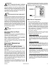
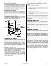
Burner Fan Air Switch
The differential in air pressure is measured by the burner fan
air switch, which is located next to the burner fan motor. If the
combustion air is inadequate, this switch will prevent ignition.
The setting of this switch is adjustable, and it should be set
at approximately 0.59-inches (15 mm) of water column (W.C.)
because of slight variances in spring tension characteristics,
range settings, and markings are nominal.
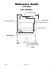
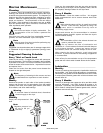
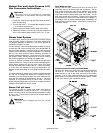
Burner Fan and Motor
The combustion air is produced by a 6-1/4" squirrel cage fan
attached to a 1-1/2 hp, 3,600 rpm motor. The motor must
spin counterclockwise (CCW) as viewed from the rear of the
motor.
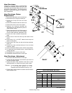
Combustion Air Lint Filter
The combustion air lint filter is made of a fine mesh stainless
steel screen which must be cleaned regularly. This screen
prevents any lint from entering the burner box.
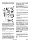
Combustion Air Damper
To produce the required combustion airflow, this damper can
be adjusted. Remove the screen to get access to the damper.
Moving the damper closer to the blower inlet opening will
reduce the combustion airflow, and moving it away from the
blower inlet opening will increase the airflow. To measure
the combustion airflow, attached a manometer to the air
pressure tap on the burner box. The air pressure should
measure 1.25- inches (31.75 mm) to 1.5-inches (38.1 mm)
W.C.
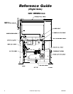
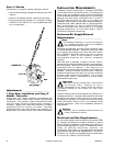
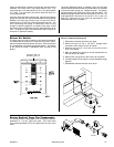
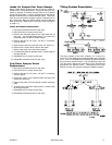
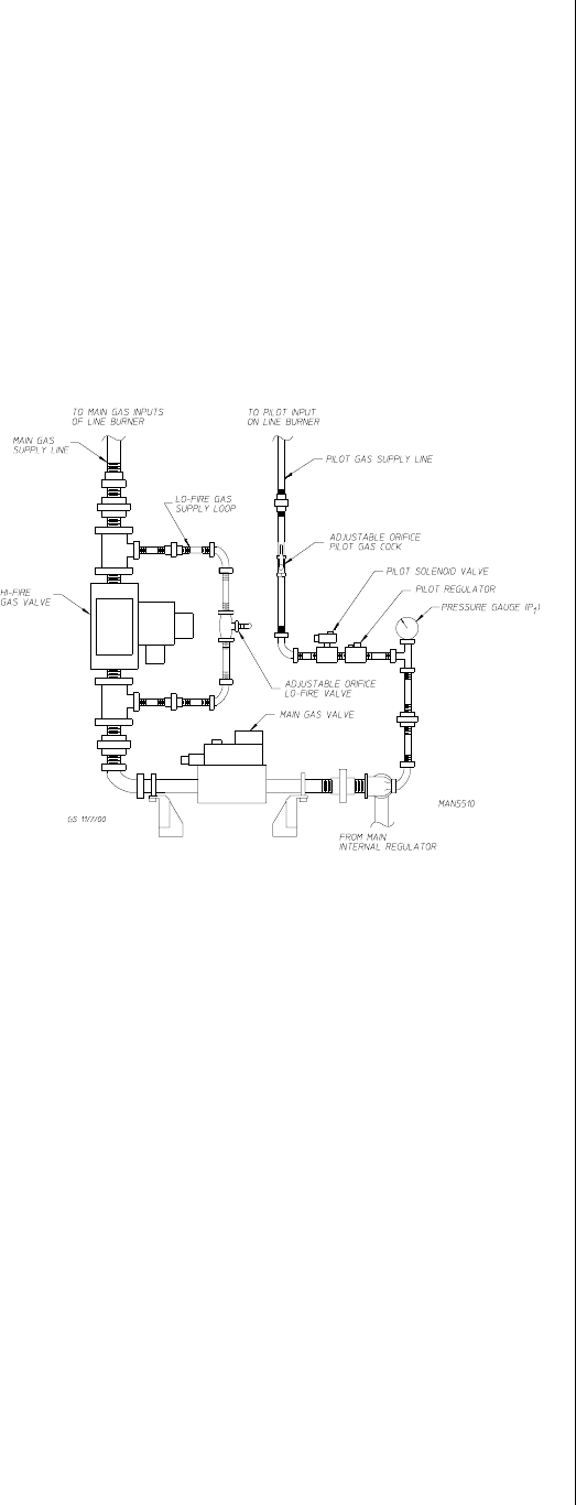
Pilot Gas Supply Line ________________
The pilot gas supply line consists of a manual shutoff valve,
pressure regulator, electric solenoid valve, back-loaded
pressure regulator, and an adjustable gas cock.
The gas pressure in this line should be approximately
3.5-inches (88.9 mm) W.C. for natural gas and 1.5-inches
(38.1 mm) W.C. for liquid propane (L.P.) gas. This will provide
a bushy pilot flame, which produces a signal through the
flame rod that is converted to 3 to 11 volts DC in the burner
controller module (BMC).
This flame can be adjusted in two (2)
ways
Pilot Inlet Pressure Regulator
Remove the cap and turn the slotted adjustment screw
clockwise (CW) for more gas and counterclockwise
(CCW) for less gas.
Adjustable Pilot Gas Cock
Remove the cap and turn the slotted adjustment screw
clockwise (CW) for less gas and counterclockwise (CCW)
for more gas.
The pilot line contains a back-loaded pressure regulator with
an impulse line connected to the gas burner inlet. The
regulator will maintain a constant pilot supply pressure in
the burner due to an increase in temperature. Do not adjust
this regulator.
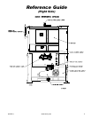
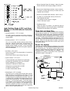
Main Gas Supply Line ________________
The main gas supply line consists of a pressure regulator,
two (2) motorized shutoff valves, HI/LO gas pressure switch,
manual shutoff valve.
The gas pressure at the burner should be 2.5-inches
(63.5 mm) W.C. for natural gas and 1.25-inches (31.8 mm)
water column for L.P. gas. This pressure is measured by a
manometer at the manual shutoff valve just top motorized
valve.
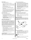
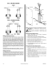
Motorized Gas Valve
The two (2) 2-inch F.P.T. motorized valve are ON/OFF gas
flow control valves. The valves motors operate on 120 VAC
and are electrically cascaded so that upper valve will not
open until lower valve has fully opened. A limit switch inside
the lower motorized valve provides the signal that the valve is
fully opened. These valves will open only when the BCM is
receiving a signal from the flame rod proving that the pilot
flame is established. The bypass of the second valve allows
for the low fire.
Top Motorized Gas Valve
The valve sets the gas rate of 2,800,000 Btu/hr (705,290
kcal/hr). To achieve this rate, the gas pressure must be set
for 2.5-inches (63.5 mm) water column for natural gas and
1.25-inches (31.8 mm) W.C. for L.P. gas. To adjust. loosen
the pan head screw located on the front of the top motorized
valve, while holding the valve body, turn the flow adjustment
clockwise (CW) for less gas and counterclockwise (CCW)
for more gas. Retighten the pan head screw when correct
gas flow is achieved. There is a switch located on the back of
the top gas valve that verifies valve closure. The BCM will go
into a system unsafe error and the burner will not begin a
burner sequence.