


450260-1 www.amdry.com 33
!
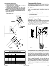
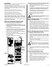
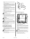
Programmable Logic Controller (PLC) Replacement
1. Discontinue electrical power to the dryer.
2. Mark and identify the wires that will be removed for proper
reinstallation.
3. To remove the PLC from the mounting rail, using a
screwdriver, very carefully pull out the mounting clip on
the bottom of the PLC and lift the unit out of the rail.
4. To replace the PLC, push in the top of the PLC into the
rail and then snap in the bottom of the unit.
5. Replace the wires removed in Step #2.
6. Reestablish electrical power to the dryer.
Note
Allen Bradley Micrologic 1200 terminals can be
removed by screws at each end without removing
any wires from the terminal strip.
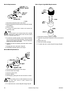
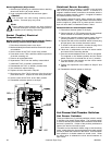
Phase 7 Microprocessor Controller (Computer)
Display Board Replacement
1. Discontinue electrical power to the dryer.
2. Carefully unplug JPD3 connector, the JPD4 connector,
and the keyboard (touch pad) ribbon cable.
3. Disconnect the common connector power cable (JPD6).
4. Loosen and remove the two (2) screws securing the
Phase 7 microprocessor controller (computer) display
board and then remove the computer from the door.
5. To install new Phase 7 microprocessor controller
(computer) display board, reverse Step #4 through Step
#1.
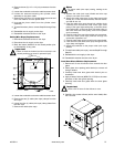
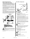
Phase 7 Microprocessor Controller (Computer)
Input/Output (I/O) Board Replacement
1. Discontinue electrical power to the dryer.
2. Carefully unplug the connectors from JPM9, JPM7,
JPM11, JPM8, JPM10, JPM1, JPM2, JPM3, and JPM4.
Stamped on the microprocessor controller (computer)
I/O board.
3. Remove the five (5) Phillips head screws securing the
I/O board to the control panel.
4. Carefully remove the I/O board from the two (2) standoffs.
Note
For replacement of the new I/O board it is important to
handle with care to avoid any electrical shocks.
Damage may occur. Proper static precautions should
be taken.
5. To install new microprocessor controller (computer)
input/output (I/O) board, reverse Step #4 through
Step #1.
6. Reestablish electrical power to the dryer.
Keyboard (touch pad) Replacement
1. Discontinue electrical power to the dryer.
2. Disconnect keyboard (touch pad) ribbon cable from the
Phase 7 microprocessor controller (computer) display
board.
3. Peel existing keyboard (touch pad) from the door.
4. Remove as much of the remaining adhesive (from the
removed keyboard [touch pad]) as possible.
5. Install and adhere new keyboard (touch pad).
6. Reestablish electrical power to the dryer.
Output Relays
Output relay #0 (drive forward) and output relay #1 (drive
reverse) are used to perform jog functions.
Output relay #2 controls the open front door function. When
this signal is energized, the pneumatic valve opens allowing
air into the two (2) door cable cylinders, which in turn opens
the front doors.
Output relay #3 controls the front UP solenoid.
Output relay #4 controls the front DOWN solenoid.
Output relay #5 controls rear doors open.
Output relay #6 controls the rear UP solenoid.
Output relay #7 controls the rear DOWN solenoid
Output relay #8 controls dry enable. This gives control to the
Phase 7 board to start the drying process. This signal is
present when all the doors are closed and the dryer is level.
Output relay #9 controls supply air. This controls the air valve
supplying air to all the dryer.
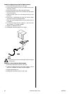
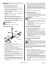
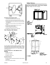
Electrical Component Replacement
Control Voltage Transformer Replacement
1. Discontinue electrical power to the dryer.
2. Locate the correct schematic for the specific change(s)
required and verify the wiring of the transformer using
the schematic.
3. Verify the voltage of the new transformer.
4. Loosen and then remove the four (4) wires for a
208-240 VAC dryer or the six (6) wires for a 380 VAC
(and higher) dryer from terminal block #3 (TB3).
5. Remove the four (4) screws securing the transformer,
then remove the transformer itself.
6. To install new transformer reverse above steps (Step
#5 through Step #2).
7. Reestablish electrical power to the dryer.
!