


32 American Dryer Corp. 450260-1
Phase 7 Microprocessor Controller (Computer)
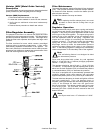
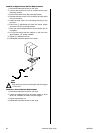
The temperature sensor probe is a bullet shaped device that
is located in the exhaust duct by the heat reclaimer. This
temperature sensor probe is used to sense the temperature
in the exhaust of the dryer. The temperature sensor is a two
(2) terminal monolithic integrated circuit temperature
transducer that provides an output current proportional to
absolute temperature. The transducer acts as a high
impedance temperature dependent current source of
1mA/ºK. The typical accuracy of this probe is +/- 1.5º C
(+/- 2.7º F). In a case where the temperature reaches 220º F
(104º C), the Phase 7 microprocessor controller (computer)
will shut down and the light emitting diode (L.E.D.) will display
Exhaust High Temp Fault. To restart a cycle the
STOP/CLEAR button must first be pressed.
To check a temperature sensor you first need a digital
multimeter (DMM) with a diode check position. Put the meter
on diode check, place the red lead of the meter on the black
lead of the temperature sensor and the black lead of the
meter on the white temperature sensor wire. At this point
you should get no response from meter (infinite). If you get a
reading the temperature sensor is defective.
Next reverse leads to temperature sensor black to black
and red to white. At that point you measure approximately
1.8-amps, this is the turn on voltage of the device. If you hold
the temperature sensor in your hands and warm it the reading
will decrease corresponding to a higher current flow (the
decrease is very slight tenths of a volt).
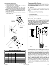
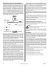
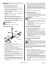
The rotational sensor is a magnetic proximity switch that is
mounted on the basket (tumbler) wrapper on the left side of
the dryer. There is a magnet mounted to the side of the
basket (tumbler). After each rotation of the basket (tumbler),
the magnet passes by the proximity switch causing the
contacts to close and pulse the Phase 7 microprocessor
controller (computer). Whenever the magnet is over the
proximity switch there should be contact closure.
When a drying cycle is started, the blower (fan and impellor)
output switches on putting 24 VAC on the blower (fan and
impellor) contactor coil, which in turn pulls in the contactor
starting the blower motor turning. The Phase 7 board passes
through a Fan On signal to the programmable logic
controller (PLC) disabling the tilting function. Moments later,
the basket (tumbler) and drum begin to rotate because the
output turns on thereby pulling in the basket (tumbler) and
drum forward contactor. Next, the heat On/Off output will
turn on if there is a call for heat, supplying 24 VAC to the heat
circuit through the safety circuits.
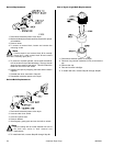
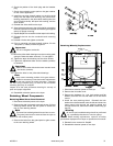
The first safety circuit is the manual reset exhaust hi-limit,
which is located on the bracket with the temperature sensor
probe in the exhaust duct. On a temperature rise of 235º F
(113º C) or higher, the thermal switch opens breaking the
heat circuit, this switch must be manually reset.
A second safety circuit is the burner automatic reset hi-limit
switch located on the top of the burner. On a temperature
rise of 330º F (166º C) or higher, the thermal switch opens
breaking the heat circuit.
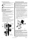
A third safety circuit is the sail switch, which is located on the
side of the lint drawer. This device pulls in when the impellor
(fan and blower) is operating correctly and verifies proper
airflow.
If all the safeties are properly maintained and a call for heat
is present, 120 VAC will enable the Burner Control Module
(BCM) via programmable relay 3 on the Phase 7 board
through the gas pressure switches.
The heat output from the Phase 7 will enable the gas valves
and open the heat reclaimer.
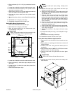
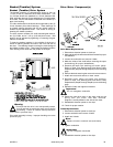
Programmable Logic Controller (PLC)
The PLC can consist of one (1) or two (2) modules; a main
module and in some cases an expansion module is used
for additional inputs and outputs.
Note
The information listed is generic in nature, refer to
blueprints for specific details.
The PLC module has fourteen (14) input relays, which are
labeled #0 through #13 and ten (10) output relays labeled #0
through #9.
Input Relays
Input relays #0, #1, #2, and #3 are set up as user inputs to
signal what specific function is to be performed (i.e., load,
unload, tilt, and front identifier). These input relays are charted
as 1 and 0 (1 is logic on and 0 is logic off). When either an
input relay or an output relay is on, the appropriate L.E.D. on
the PLC will be illuminated.
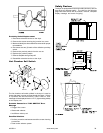
For input relay #7 to turn on, the top and bottom front doors
must be completely open. Once these doors are completely
open, the jog forward (input #4) and jog reverse (input #5)
can turn on through the PLC, which in turn rotates the basket
(tumbler) and drum through either output relay #0 or output
relay #1 providing the lint door is closed. This interlock is
performed through PLC input #9 (lint door closed), or in some
cases the drive or blower overload may interrupt the 24 VAC
signal from reaching the drive contactors and the tilting
solenoids.
Input relay #6 indicates that the blower fan is ON. This input
is used to disable the outputs while the fan is on indicating
that the dryer is drying.
Input relay #8 indicates the front doors are closed.
Input relay #10 indicates the front is down.
Input relay #11 indicates the rear is down.
Input relay #12 indicates the rear doors are open.
Input relay #13 indicates the rear doors are closed.
!