


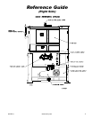
450260-1 www.amdry.com 9
COMPONENT DESCRIPTION/
REPLACEMENT _________________
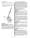
Gas Burner and Ignition System ____
The dryer's gas burner system operates on an On or Off
gas rate sequences to accurately control the tumblers
(basket's) drying temperature. Maximum firing rate is 2.8
million Btu/hr.
Upon a call from heat, the dryer computer sends a 120 volt
signal to the burner controller module (BCM) which initiates
and controls the ignition sequences. The BCM insures that
all the safety switches are closed before turning on the
combustion air burner fan, then checks to ensure that the
burner fan air switch has closed. The pilot gas flame is then
established, the flame rod, (which sits in this pilot flame),
comes in contact with the flame and signals the BCM. The
main motorized gas valves open in sequence, and full
operational flame is achieved.
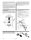
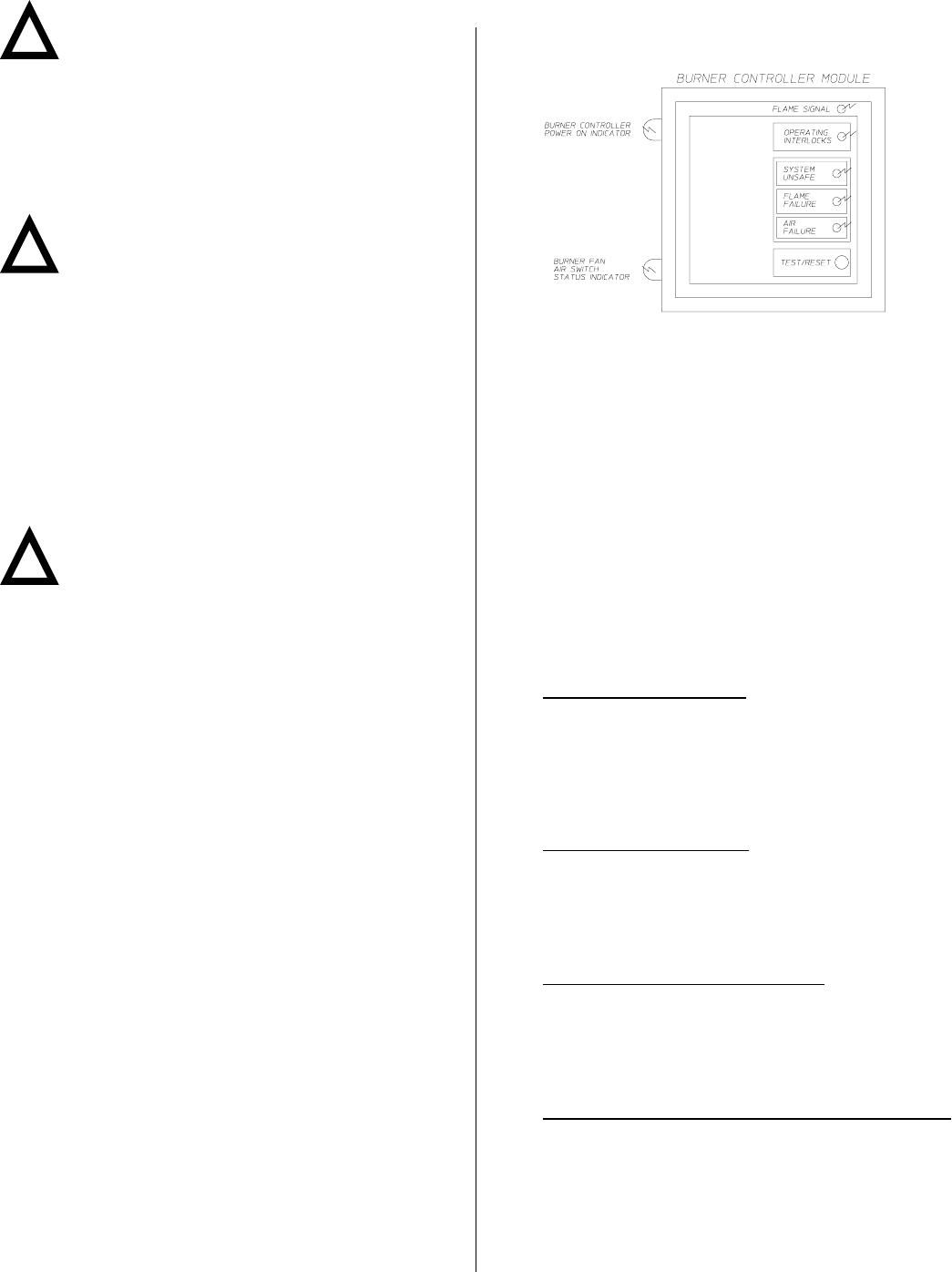
The BCM has five (5) light emitting diodes (L.E.D.) on its
cover and two (2) neons on the mounting base for ease of
troubleshooting, as well as dip switches inside for ease of
programming.
!
MAN2374
!
!
Impor tant
Failure to comply with these codes or ordinances
and/or the requirements stipulated in this manual
can result in personal injury or component failure.
The dryer installation must meet the American National
Standard, National Fuel Gas Code ANSI Z223.1-LATEST
EDITION, or in Canada, the Canadian Electrical Codes Parts
1 & 2 CSA C22.1-1990 or LATEST EDITION (for Electrical
Connections) as well as, local codes and ordinances, and
must be done by a qualified technician.
Note
Undersized gas piping will result in ignition problems
and slow drying and can create a safety hazard.
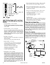
The dryer must be connected to the type of gas (natural or
liquid propane [L.P.]) indicated on the dryer data label. If this
information does not agree with the type of gas available,
contact the reseller who sold the dryer or contact the factory.
The gas input ratings shown on the dryer data label are for
elevations up to 2,000 feet (609.6 meters), unless elevation
requirements of over 2,000 feet (609.6 meters) were specified
at the time the dryer order was placed with the factory. The
adjustment for dryers in the field for elevations over 2,000
feet (609.9 meters) is made by changing the burner orifices.
If this adjustment is necessary, contact the reseller who sold
the dryer or contact the factory.
Note
Any burner changes must be made by a qualified
technician.
Operational Service Check
Procedure ____________________________
After performing any service or maintenance function, an
operational check should be performed to ensure that all
components are performing properly.
Make a complete operational check of all the operating
controls to ensure that the timing is correct, temperature
selection switches are functioning properly.
Make a complete operational check of all safety related
circuits, door switches, hi-limit thermostat, sail switch, cycling
thermostats, etc.
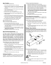
The BCM controls all of the gas burner ignition components,
except for the motorized gas valve. When the drying set point
temperature is reached, the dryers computer closes the top
motorized gas valve, shutting off full flame.
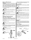
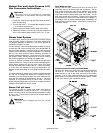
Major Burner Components
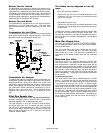
Burner Controller Module (BCM)
The BCM provides effective burner flame safeguard
control through adjustable purge and trial-for-ignition
timing. The BCM insures that all dryer safety switch
circuits are closed, delays ignition to allow the
combustion chamber to vent, and insures that a healthy
pilot flame is established before opening the main gas
valves. Five (5) L.E.D.s on the cover of the BCM allow for
easy troubleshooting. Dip switches on the back of the
module allow for easy programming.
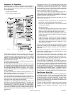
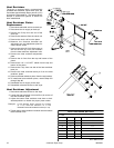
Dip Switches Selections
Loosen the two (2) screws on the burner control module
cover and pull the module cover off of its base. The dip
switches are on the back of the cover.
Switch #1 - Recycling Mode
With this switch in the ON position, the burner will
recycle the ignition sequence once during each drying
cycle after a burner fan air switch or main flame failure,
but only if the failure occurs more than 35-seconds after
ignition. If this switch is OFF," the burner will lock out at
once.
Switch #2 - Intermittent Pilot
This switch is ON for intermittent pilot or OFF for
interrupted pilot. The dryer utilizes interupted pilot so
that the pilot flame doesnt stay lit during the entire drying
cycle. With interrupted pilot, the pilot flame goes out
once the main flame is established.
Switch #3 - Trial for Ignition (TFI) Time
When this switch is ON a Trial for Ignition (TFI) of ten
(10) seconds is set. If it is in the OFF position, the TFI
is five (5) seconds. The Trial for Ignition Time is the
length of time that the pilot is given to light. A ten (10)
second TFI is best for the dryer.
Switch #4, Switch #5, Switch #6, Switch #7- Purge Time
Switch #8 is for post purge selection. With switch #8 in
the "ON" position, the post purge time will be
15-seconds. When switch #4, switch #5, switch #6, and
switch #7 are in the OFF position, the post purge time
will be 0-seconds.