Chapter 7O Agilent 10737L and Agilent 10737R Compact Three-Axis
Interferometers
Description
User’s Manual 7O-3
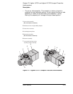
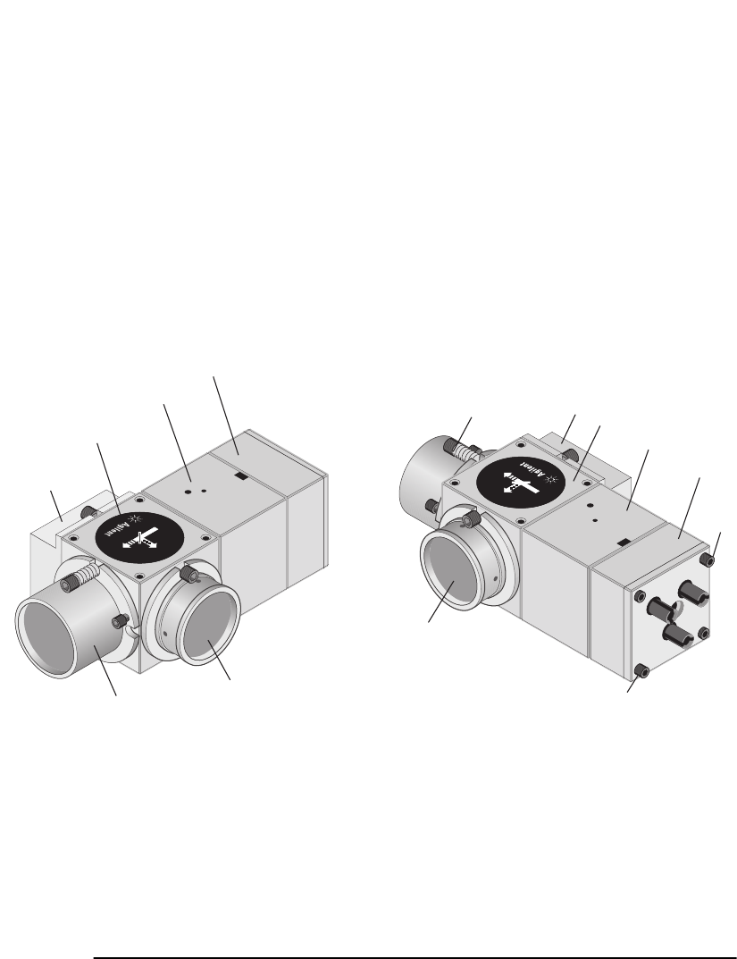
• The corner cube assembly. This assembly is factory-aligned to
produce the required beam pattern. Do not remove the corner cube
assembly or loosen the screws holding the assembly in place.
Moving this assembly will change the output beam pattern.
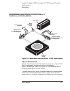
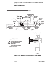
Figure 7O-1. Agilent 10737L Compact Three-axis Interferometer
3
1
3
1
5
6
7
7
2
4
2
5
6
4
1
0
7
3
7
L
3
-
A
X
I
S
I
N
T
E
R
F
E
R
F
E
R
O
M
E
T
E
R
1
0
7
3
7
L
3
-
A
X
I
S
I
N
T
E
R
F
E
R
F
E
R
O
M
E
T
E
R
1
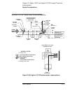
Corner cube assembly
(Do not loosen or remove)
2
Reference mirror or high stability adapter
3
Plane mirror converter
4
Polarizing beam splitter
5
Shear plate assembly
(Do not loosen or remove)
6
Receiver assembly
7
4-40 socket-head cap screws
attaching receiver assembly
10
7
03
L
10737
R


