


Chapter 7O Agilent 10737L and Agilent 10737R Compact Three-Axis
Interferometers
Procedure
User’s Manual 7O-19
Aligning the measurement beam path
1 Remove the receiver assembly and high stability adapter, as described
in the respective procedures, above.
2 Install the interferometer so the beam from the laser source enters its
input aperture and is normal to its input face.
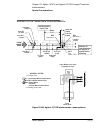
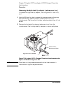
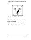
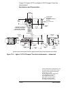
3 Set the alignment aid (Agilent Part Number 10706-60001) on the
interferometer’s Measurement beam aperture as shown in
Figure 7O-8.
With the alignment aid installed, the beam will be reflected off the
stage mirror back to the laser head.
4 Set the laser head to the small aperture.
5 Roll and yaw the interferometer until the autoreflected beam is
centered on the small aperture of the laser.
6 Select the laser head’s large output aperture and translate the
interferometer horizontally until the input beam is centered on the
interferometer’s input aperture.
A piece of translucent tape over the interferometer’s input aperture
will make the input beam visible. This procedure assumes that the
vertical height of the beam was set before the interferometer was
installed, (see the “Initial installation and setup” procedure);
alternatively, fixturing for a vertical adjustment for the interferometer
may be used.
7 Select the laser head’s small output aperture and check that the beam
is still autoreflecting.
8 Repeat steps 3 through 7 until the beam is both autoreflecting and
centered on the interferometer's input aperture.
9 Tighten all mount adjustment screws.
10 Remove the alignment aid.
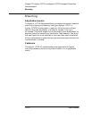
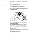
11 Check the position of the beams in the interferometer’s output
apertures (see Figure 7O-9).
Once again, translucent tape is helpful for viewing the beams in the
apertures. If any beam clipping occurs, or if the beams are far off from
the desired location, check for obstructions and recheck the alignment
(by performing steps 3 through 7 above).