


Chapter 7O Agilent 10737L and Agilent 10737R Compact Three-Axis
Interferometers
Procedure
User’s Manual 7O-21
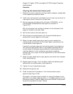
Aligning the reference beam path
NOTE The measurement path must be aligned and the laser beam centered
on the input aperture before aligning the reference mirror.
1 Remove the receiver assembly and the plane mirror converter (see
figures 7O-1 and 7O-4), and set aside on a clean surface. Do not touch
any glass surface of any optic.
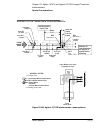
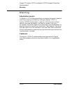
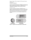
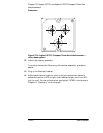
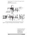
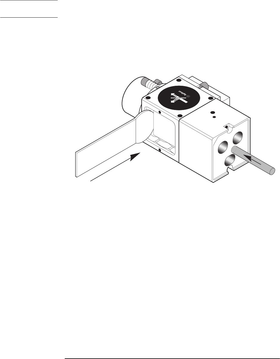
Figure 7O-10. Agilent 10737L Compact Three-Axis Interferometer
with 10706-60202 Alignment Aid
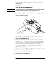
2 Install the reference mirror assembly (see figures 7O-1 and 7O-4).
The 4-40 screws on springs hold the mirror in place. The four 2-56
screws tilt the mirror for alignment. Back off the 2-56 screws so the
mirror housing is flush with the interferometer. Tighten the
4-40 screws to compress the springs completely and then back off
approximately 1-1/2 turns.
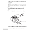
3 Place the 10706-60202 alignment aid between the beam splitting cube
and the reference mirror (see Figure 7O-10).
4 Block the beams going to the stage mirror.
5 Set the laser to the small aperture.
Input
Beam
Alignment Aid
10706-60202
1
0
7
3
7
L
3
-
A
X
I
S
I
N
T
E
R
F
E
R
F
E
R
O
M
E
T
E
R
107
3
7L