


Chapter 7O Agilent 10737L and Agilent 10737R Compact Three-Axis
Interferometers
Procedure
User’s Manual 7O-17
Installing and aligning an interferometer
CAUTION In performing the procedure below, perform only the removal,
disassembly or assembly steps described. Do not remove or take apart
anything you are not instructed to. Do not touch any glass surface or
allow it to be scratched, dirtied or otherwise harmed.
CAUTION Do not touch any glass surface of any optic. For cleaning instructions,
see Chapter 10, “Maintenance,” in this manual.
Perform this procedure for each interferometer in your measurement
system.
This procedure assumes that the laser head and all optics except the
interferometer(s) have been installed and that the appropriate beam
path(s) to the stage mirror(s) have been established as described in
Chapter 4, “System Installation and Alignment,” of this manual.
The procedure has these major parts:
1. Removing the receiver assembly
2. Removing the high stability adapter (reference mirror)
3. Aligning the measurement beam path
4. Aligning the reference beam path
5. Comparing beam path alignments
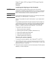
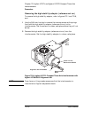
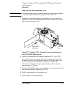
Removing the receiver assembly
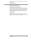
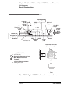
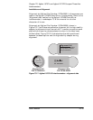
To remove the receiver assembly, refer to figures 7O-1 and 7O-8.
1 Use the 5/64-inch hex key to remove the two cap screws that hold the
receiver assembly to the interferometer. Set the screws in a clean, safe
place where they will not be lost.
2 Remove the receiver assembly from the interferometer. Set the receiver
assembly in a clean, safe place.