


63
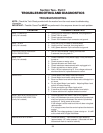
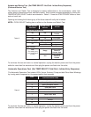
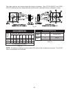
Table 12
RESISTANCE VALUES
Part Rating
Verified
Harness
Pin No. &
Wire Color
Harness
Pin No./
Part I.D.
Resistance
Reading
ΩΩ
ΩΩ
Ω
Harness/
Power Cord
Harness/
Power Cord
Clockwise motor
agitate & spin
Counterclockwise
motor agitate
Pump
Cold Valve
Hot Valve
Harness/
Power Cord
to
to
to
to
to
to
to
to
10
(G)
1
(W)
6
(BK)
5
(P)
5
(P)
4
(BK/W)
4
(BK/W)
4
(BK/W)
9
(BR)
8
(Y/R)
2
(BU)
7
(Y)
3
(R)
Power
Cord
Ground
Power
Cord
Ground
Power
Cord L1
Less than
5
ΩΩ
ΩΩ
Ω
Less than
5
ΩΩ
ΩΩ
Ω
Less than
5
ΩΩ
ΩΩ
Ω
800-1200
ΩΩ
ΩΩ
Ω
800-1200
ΩΩ
ΩΩ
Ω
3-10
ΩΩ
ΩΩ
Ω
700-1000
ΩΩ
ΩΩ
Ω
700-1000
ΩΩ
ΩΩ
Ω
4
8
1
3
2
5
6
7
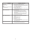
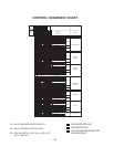
Spin
Wash
Rinse
Wash/Rinse
Spin
Wash/Spin
Spin/Rinse
Wash/Spin/Rinse
CYCLE SELECT POSITION
(Turn Clockwise)
LED
INDICATOR
Table 10
Cold/Cold (CC)
Warm/Warm (WW)
Warm/Cold (WC)
Hot/Cold (HC)
TEMPERATURE
SELECT POSITION
LED
INDICATOR
Spin
Rinse
Wash
All Off
Table 11
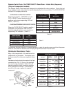
To terminate this test and return to normal operation, unplug the washer power cord from the power
outlet for more than five seconds and then plug the power cord back into the outlet.
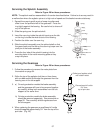
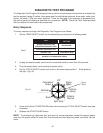
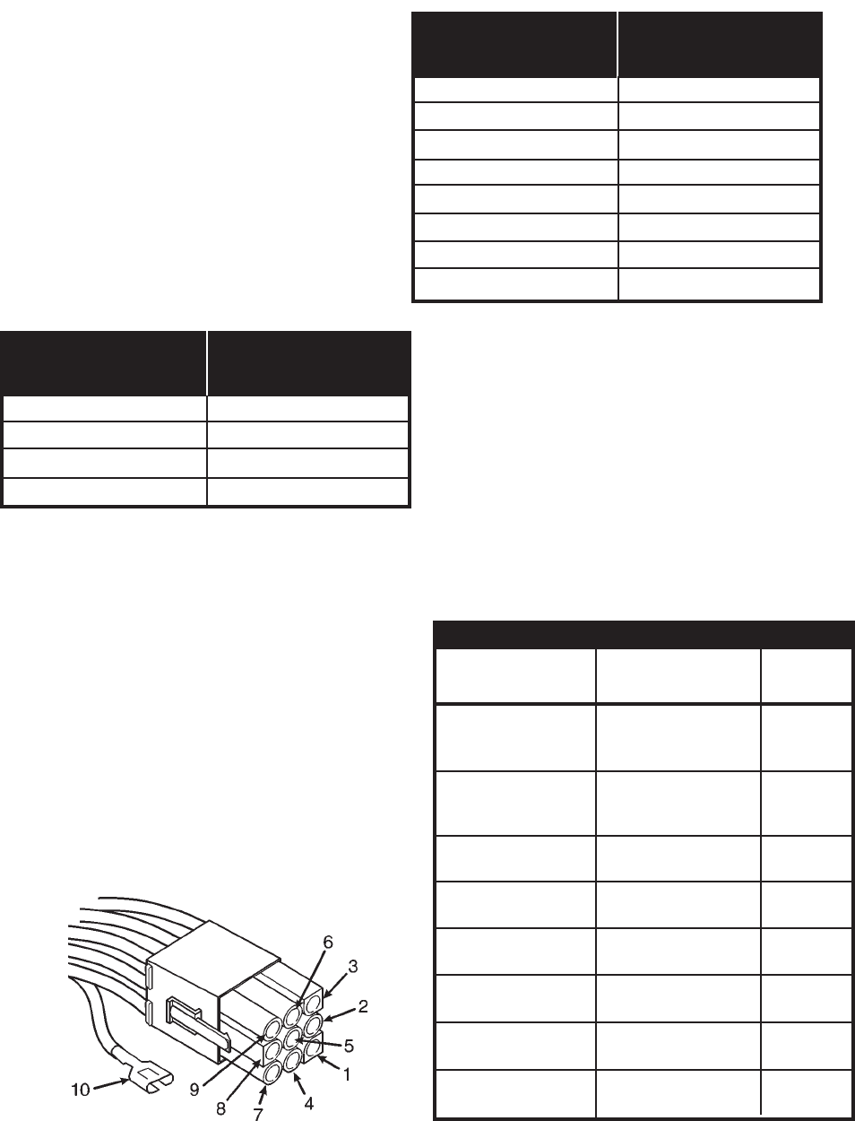
Many of the components of the washer can be
checked with an ohmmeter. The washer must
be disconnected from the power supply for these
tests.
Resistance checks should be made at the 9-pin
connector first.
(Fig. 31)
If any of the readings
are out of range as stated in
Table 12
or not
operating properly check resistance readings
at the component terminals. If the readings
are still out of range, replace the suspect
component.
Ohmmeter Resistance Tests
(Y)
(Y/R)
(BK/W)
(W)
(P)
(BU)
(R)
(BK)
(G)
(BR)
Figure 31
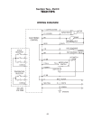
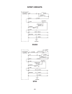
Selector Switch Tests (Set TEMP SELECT: Warm/Warm - Initiate Entry Sequence)
(Only on 4-temperature models)
The Selector Switch Tests have been designed to troubleshoot the rotary switches. During this test
every position of each rotary switch is read and decoded by the microcontroller. The CYCLE/STATUS
indicator LEDs display test results.
• CHECKING CYCLE SELECT SWITCH
Beginning at position 1 (NORMAL) turn the
CYCLE SELECT switch clock-wise to all
positions and note corresponding LED indi-
cators.
(Table 10)
• CHECKING TEMPERATURE SELECT SWITCH
Place the CYCLE SELECT switch in position 1
(NORMAL) and rotate the TEMP SELECT
switch through all positions and note the cor-
responding LED indicators.
(Table 11)