


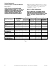
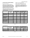
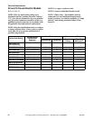
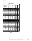
Steam Requirements
M414905
48
© Copyright, Alliance Laundry Systems LLC – DO NOT COPY or TRANSMIT
Piping Recommendations
● Trap each steam coil individually. Always keep
the trap clean and in good working condition.
● When tumbler is on the end of a line of
equipment, extend header at least 4 feet (1.2 m)
beyond tumbler. Install shut-off valve, union,
check valve and bypass trap at end of line. If
gravity return to boiler, omit trap.
● Insulate steam supply and return lines for safety
of operator and safety while servicing tumbler.
● Keep tumbler in good working condition. Repair
or replace any worn or defective parts.
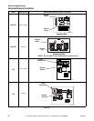
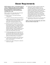
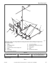
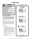
Installing Steam Trap and Making
Condensate Return Connections
The steam trap must be installed and the coil outlet
connections must be connected to the condensate
return lines. The following steps outline the procedure
for installing the steam trap and connecting the
condensate return lines. Refer to Figure 23 for typical
installations.
1. Use flexible lines between steam inlet solenoid
and steam coils, as well as outlet between steam
coil and traps.
2. If necessary, install a strainer at the end of each
flexible hose.
3. Install a steam trap to each strainer.
IMPORTANT: Steam trap must be installed a
minimum of 18 inches (457 mm) below the steam
coil outlet connections.
4. Install a shut-off valve to each steam trap.
5. Connect to the condensate return lines.
6. For steam solenoid valve wiring connections,
refer to Wiring Diagram supplied with tumbler.
Thermal Oil Prep
It is the responsibility of the customer to install
appropriate coil and heating system for thermal oil
prep models. Alliance Laundry Systems, LLC. is not
responsible for the performance or safety of the
customer installed thermal oil system. To ensure
proper operation, refer to the Specifications and
Dimensions section for the BTU input of equivalent
steam models. Thermal oil systems that do not deliver
appropriate BTUs will dry slower. For solenoid valve
wiring connections, refer to the Wiring Diagram
supplied with tumbler.
WARNING
All system components must have a
125 psig (8.6 bar) working pressure.
Shut-off valves must be installed upstream
of the steam solenoid valve and
downstream of each steam trap so
components can be isolated for
maintenance or emergency purposes.
All components (solenoid valve, traps)
must be supported to minimize loads on
the tumbler steam coil connections.
W480R2
WARNING
The flexible steam hoses connecting the
coil outlet connections and steam traps
must have a minimum of 125 psig
(pounds per square inch gauge) (8.79 kg/
sq. cm.) working pressure. A shut-off
valve must be installed downstream from
each steam trap so the condensate return
line can be isolated in event a steam trap
requires maintenance.
Each steam trap must be supported so
minimum load is exerted on the coil outlet
connection.
W066