


M414905
16
© Copyright, Alliance Laundry Systems LLC – DO NOT COPY or TRANSMIT
Installation
Pre-Installation Inspection
Upon delivery, visually inspect the crate, carton and
parts for any visible shipping damage. If the crate,
carton, or cover is damaged or signs of possible
damage are evident, have the carrier note the condition
on the shipping papers before the shipping receipt is
signed, or advise the carrier of the condition as soon as
it is discovered.
Remove the crate and protective cover as soon as
possible and check the items listed on the packing list.
Advise the carrier of any damaged or missing articles
as soon as possible. A written claim should be filed
with the carrier immediately if articles are damaged or
missing.
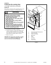
IMPORTANT: Remove the shipping tape from the
two back draft dampers located in the exhaust
outlet.
IMPORTANT: Warranty is void unless tumbler is
installed according to instructions in this manual.
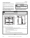
Installation should comply with minimum
specifications and requirements detailed in this
manual and applicable local gas fitting regulations,
municipal building codes, water supply regulations,
electrical wiring regulations, and any other
relevant statutory regulations. Due to varied
requirements, applicable local codes should be
thoroughly understood and all pre-installation
work arranged for accordingly.
IMPORTANT: Keep tumbler area clear and free
from combustible materials, gasoline and other
flammable vapors and liquids.
NOTE: 3 Phase Only – Each tumbler must be
connected to its own individual branch circuit
breaker, not fuses, to avoid the possibility of “single
phasing” and causing premature failure of the
motor(s).
Materials Required (Obtain Locally)
All Models
One Single Pole fused disconnect
switch or circuit breaker on 1 Phase
models.
Circuit breaker on 3 Phase models.
Gas Models
One gas shut-off valve for gas service
line to each tumbler.
Steam Models
One steam shut-off valve for steam
service line to be connected upstream of
solenoid steam valve.
Two steam shut-off valves for each
condensate return line.
Flexible steam hoses with a 125 psig
(pounds per square inch gauge)
(8.79 kg/sq. cm) working pressure for
connecting steam coils. Refer to Figure
23 for sizing and connection
configurations.
Two steam traps for steam coil outlets
to condensate return line.
Optional – Two vacuum breakers for
condensate return lines.