


12
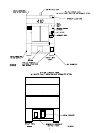
SYSTEM LADDER DIAGRAM
The SYSTEM LADDER DIAGRAM is an overview on the electrical connections of the ML-410. This diagram
is for signal flow information and is a tool to direct an individual in the correct direction for troubleshooting this
machine.
The ML-410 system is divided into a number of electrical sections which are as follows:
1. Right Front Control Panel
The RIGHT FRONT CONTROL PANEL is located in the Right Front Control Cabinet of the ML-410.
This panel is the heart of the drying system, where ALL control signals interface to or from this panel. The
signals that interface to this panel are too many to list here, however, they are ALL identified on TB1 of its
schematic diagram.
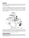
2. Right Base Electrical Enclosure
The RIGHT BASE ELECTRICAL ENCLOSURE is located towards the front of the right base section. An
industrial multi-pin connector is used to connect the base section control signals to the tumbler (basket)
sections main control panel. This electrical enclosure is labeled CAUTION, HIGH VOLTAGE IS
PRESENT IN THIS ENCLOSURE and incorporates the following electrical devices:
The MAIN ELECTRICAL POWER to the machine
The ELECTRICAL CONNECTION for the OPTIONAL SPRINKLER CIRCUIT POWER
The THERMAL/MAGNETIC OVERLOAD and CONTACTOR for the BLOWER MOTOR
3. Right Base Interface Junction Box
The RIGHT BASE INTERFACE JUNCTION BOX is located towards the rear of the right base section and
is used as a central location to interface the base section electrical components to the TILTING tumbler
(basket) section. An industrial multi-pin connector is used to connect the base section control signals to the
tumbler (basket) sections main control panel. The control signals incorporated in the Right Base Interface
Junction Box are:
SOLENOID CONTROL
Front Up/Front Down
Rear Up/Rear Down
Open Front Door
Supply Air Enable
Air Jet
LINT DRAWER/STATUS
TUMBLER TEMPERATURE and HI-LIMIT INFORMATION
TUMBLER LEVEL SENSE
Front Level Switch
Rear Level Switch