


10
GAS PRESSURE
The natural gas pressure supplied to the dryer must be between 6-inches (14.92 mb) and 12-inches of W.C.
(water column) - 29.9 mb - pressure. If the supply pressure is above 12-inches water column (29.9 mb) than an
external regulator must be installed to reduce the gas supply pressure to between 6-inches (14.92 mb) and 12-
inches of water column (29.9 mb).
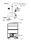
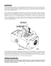
Once the flame has been established in both burner boxes, the natural gas outlet manifold pressure measured at
each gas valve pressure tap must be 3.5-inches W.C. (water column) - 8.7 mb - pressure. Connect a water tube
manometer to the 1/8 F.P.T. gas pressure tap on the downstream side of each gas valve. There is a pressure
regulator in both gas valves so the manifold pressure can be adjusted to 3.5-inches water column (8.7 mb).
Unscrew the slotted regulator cover which is located on the top of each gas valve, and turn the regulator adjustment
screw located underneath the cover (clockwise [CW] to increase manifold pressure and counterclockwise [CCW]
to decrease manifold pressure).
The L.P. (liquid propane) gas pressure measured at each gas valve pressure tap must be 11-inches water column
(27.4 mb) pressure, when the flame is established in both burner boxes. There is no means to adjust this pressure
supplied with the dryer so the downstream L.P. pressure regulator must be adjusted to provide the 11-inch water
column (27.4 mb) outlet manifold pressure. Connect a water tube manometer to the 1/8 F.P.T. gas pressure tap
on the downstream side of each gas valve to measure the manifold pressure.
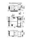
IMPORTANT INFORMATION
Once the Blower Motor starts, both the FRONT AIRFLOW SWITCH and the REAR AIRFLOW SWITCH
must pull in to indicate that there is sufficient airflow through the machine for safe ignition of both the
Front Burner and the Rear Burner.