


48
1. No Display Condition
a. Check fuse 1 or 2 and if either are blown, replace.
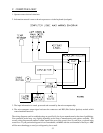
b. Take voltage reading across the microprocessor (J7) 9-pin connector pins 1 and 2. If no voltage is present
at pins 1 and 2, double check the secondary (24 VAC) side of transformer at the blower motor contactor
number 13 to ground if voltage is present. Problem is bad wire or faulty connection from blower motor
contactor #13 back through J2 9-pin connector and then to computer connector pin 1.
c. Check primary voltage to the 24 VAC transformer. (208-240 VAC). If voltage replace the transformer.
If no voltage check blower motor. Overload to see if tripped. If tripped reset, if not tripped check
incoming to power block -- (L1, L3).
NOTE: In this next section ALL voltage checks must be done in the operating mode with the
appropriate microprocessor dot on. Also appropriate L.E.D. (light emitting diode) output light
on.
NOTE: In this next section when checking for voltage you are looking for 25 AC volts unless
otherwise specified.
2. Drive motor reverses but does not forward, blower motor runs
a. If computer dot (first dot on the left) does not come on replace the computer.
b. Check for voltage across the coil of the forward contactor located in the reversing panel box. The
contactor according to your diagram is marked CR2. The coil markings A1 and A2.
If voltage is present, replace reversing contactor.
If voltage is not present, there is a bad wire or termination between BS2 and contactor coil (CR2).
c. If there is voltage across the two (2) AS2 terminals and no voltage across the two (2) BS2 terminals,
replace the arc suppressor board.
If there is no voltage across the two (2) AS2 terminals on the arc suppressor (A.S.) board, the problem is
a bad wire or termination between the AS2 board and the J7 9-pin computer connector no. 8 or faulty
computer.
3. Drive motor works in forward mode but does not reverse, blower motor runs
a. If computer dot (second one from left) does not come on, check program to see if set for reverse.
b. If set for reverse, replace computer.
c. Check for voltage across the coil of the reversing contactor located in the rear panel box. The contactor
according to your diagram is CR3, also the markings on the coil are A1 and A2.
If there is voltage, replace the coil or the complete contactor.
If there is no voltage, check for voltage across the two (2) BS3 terminals on the arc suppressor (A.S.)
board.