


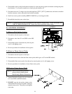

18
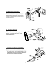
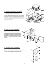
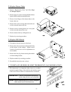
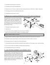
4. Disassemble sensor probe from bracket assembly by removing the top push-on fastener securing the probe
from bracket. Use a small screwdriver to slowly pry the fastener off.
5. Disconnect the two (2) orange wires from the high heat (225º F [107º C]) thermostat, and remove modular
bracket connector, wires, and probe from bracket assembly.
6. Install new sensor probe assembly (ADC P/N 880251) by reversing procedure.
7. Reestablish electrical power to the dryer.
NOTE: If, when electrical power is reestablished, the computer display reads “TEMP SENSOR FAIL
CHECK TEMP SENSOR FUSE,” check for a loose connection in the wiring.
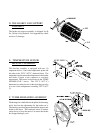
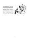
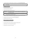
B. IGNITION CONTROLS
To Remove Hot Surface Ignitor
1. Discontinue electrical power to the dryer.
2. Disconnect wire from S1 and GND on the HSI
module.
3. Disassemble ignitor from burner by removing the
one (1) self tapping screw.
4. Reverse procedure for installation of new ignitor.
To Remove Flame Sensor Probe
1. Discontinue electrical power to the dryer.
2. Disconnect the red wire from the flame sensor probe which goes to S2 on the HSI module.
3. Disassemble flame sensor probe from burner by removing the one (1) self tapping screw.
4. Reverse procedure for installation of new flame sensor probe.
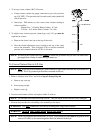
HSI Ignitor Flame Sensor Probe
NOTE: Before reestablishing electrical
power to dryer visually check
the following. (Refer to illustration):
1. That the Hot Surface Ignitor wires are connected
to S1 and GND on the HSI module.
2. DO NOT wrap the hot surface ignitor wires
and the flame electrode wire together. Improper
operation may result. They may run alongside
each other.