


4 - 2
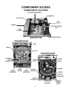
COMPONENT ACCESS
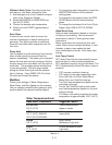
Required Tools
The Front-Loading Automatic Washer requires the use of Metric Sockets of various sizes, Torx T-20
and T-25 Drivers, a Crescent Wrench, a flat bladed screwdriver and a hammer.
ACCESSING COMPONENTS IN THE CONSOLE
Fig. 4-5
Fig. 4-4
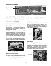
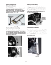
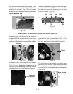
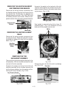
Removing the Console from the Cabinet
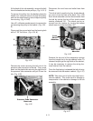
Disconnect the Touch Pad/LED Assembly ribbon
connector from the left side of the Central Con-
trol Unit
(Fig. 4-5)
and release it from the wiring
harness brackets on the right side of the washer
top.
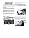
Remove the detergent
dispenser drawer by
pressing down on the
release tab at the back
of the drawer
(Fig. 4-
6A)
and pulling it com-
pletely out of the
washer.
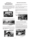
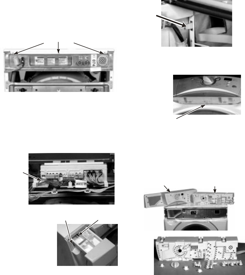
Removing the Touch Pad/LED Assembly from
the Console
Drawer
Release Tab
Screw
Fig. 4-6A
Fig. 4-7A
Fig. 4-7B
Screws
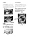
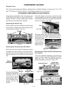
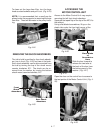
Removing the Washer Top
Three screws secure the washer top at the back
of the washer. Remove the three screws and lift
the top from the washer.
(Fig. 4-4)
Ribbon
Connector
Console Cover
Touch Pad/
LED Assembly
The Touch Pad/LED Assembly is removed as a
single unit and contains the Push Buttons, LEDs,
cable, etc.
(Fig. 4-7A)
The buttons can be re-
placed separately as shown in
Fig. 4-7B
.
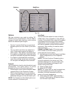
Components accessible in the Console include
the Console Cover and the Touch Pad/LED As-
sembly. Access to these components requires
that the top of the washer be removed.
Once the drawer is removed, remove the screw
in the recessed hole next to the drawer opening.
Release the tab securing the right side of the con-
sole to the washer
(Fig. 4-6B)
.
Tab
Tab
Fig. 4-6B
Open the washer door and place a flat-bladed
screwdriver into the slot in the bottom center of
the console
(Fig. 4-6C)
. Push the console up
to release center
console tab. Be
sure the ribbon
cable clears the
cabinet frame.
Fig. 4-6C