WARNI NG
!
Disassembly Procedures
To avoid risk of electrical shock, personal injury or death,
disconnect power to unit before servicing.
©2005 Maytag Services 16026502 29
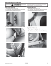
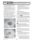
6. Remove Pressure Switch hose, Tub Springs and
Outer Tub/Transmission assembly, see “Agitator/
Spinner/Outer Tub/Transmission Removal”
procedure steps 13, 14 and 16.
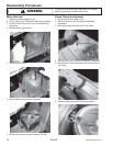
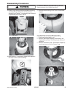
7. Remove screws from sides and rear of unit around
bottom, connecting Cabinet to Base. Remove
Cabinet from Base and set aside. Be sure to lay
down a protective pad before removing Tub and
Transmission assembly from Base. Remove Tub and
Transmission assembly, turn over and lay on
protective pad.
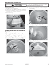
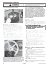
8. Remove Dust Cap, Retaining Ring, Washer, Cam,
and Drive Pulley from bottom of Transmission, see
“Drive Pully and Cam Removal” procedure.
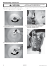
9. Remove Brake assembly from Transmission, see
“Brake Disassembly” procedure steps 4 - 12.
Remove old Snubber from Transmission.
10.Install new Snubber, see “Snubber/Brake Assembly”
procedure steps 3 - 6. Insure Snubber is centered.
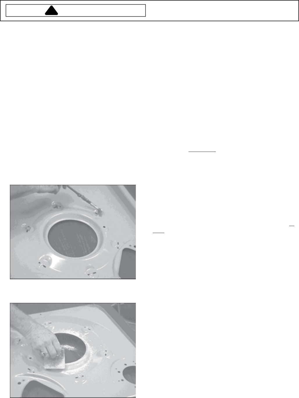
11.Turn new Base upside down and apply grease at
bottom of the spring hole pockets to eliminate noise
between Spring and Base interaction.
12.Clean the dome area of new Base with alcohol then
apply corn starch.
13.Reinstall Motor and Pump to new Base.
14.Transfer Transmission and Outer Tub onto new Base.
Attach Suspension Springs using spring tool to avoid
over stretching the Springs.
15.Transfer Cabinet shell onto new Base and
reassemble Washer. Be sure to reattach Pressure
Switch Hose to back of Tub, Drain Pump Hoses with
clamps to Drain Pump, and wire harness to Motor.
Check all hoses and wires to make sure they are
secure.
16.Test Washer.
Transmission Operation
When the Drive Pulley rotates CLOCKWISE, the upper
and lower cams are designed to nest together which
allows the Drive Pulley to remain in position on the drive
shaft. The Break remains engaged and the Drive Pulley
will turn the lower cam and drive the shaft to cause the
Transmission
to agitate.
When the Drive Pulley rotates COUNTERCLOCKWISE,
the upper cam and Pulley ride up the lower cam approxi-
mately 3/16 of an inch before the driving shoulders on the
Pulley hub engage the "dogs" on the lower cam.
This causes the top of the Pulley hub to push against the
Spacer which compresses the Brake Spring and lifts the
Brake Rotor and Lining assembly off the Brake Stator.
The Brake is disengaged and the Pulley will turn the
lower cam and drive shaft to cause the Transmission
to
spin.
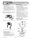
Determine Brake Rotor Condition
Watch the Spacer on the Encapsulated Thrust Bearing.
If the Spacer rotates with the Pulley, the Brake is
functioning properly. If the Spacer stays stationary while
rotating the Pulley to release the Brake, the Brake Rotor
must be replaced.
After reassembling the Washer, fill the Tub with water
and select a spin to drain the Tub. When the cycle is
finished, verify the adjustment of the Brake, and verify
the Spacer on the Thrust Bearing rotates with the Pulley.
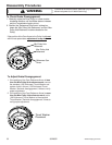
Brake Adjustment
1. After reassembling the components on the drive
shaft, it may be necessary to pull down on the shaft
to take the endplay out before the Thrust Washer
and Retaining Ring can be reinstalled.
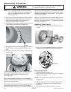
NOTE: Each time the cams are reassembled on the
drive shaft, the point in the cam rise where the
Brake disengages the Stator should be checked
and adjusted as necessary. Reference points
have been molded into the Pulley as an aid in
checking the point of Brake disengagement.


