


WARNI NG
!
To avoid risk of electrical shock, personal injury or death,
disconnect power to unit before servicing.
Disassembly Procedures
28 16026502 ©2005 Maytag Services
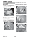
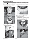
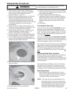
NOTE: This is a dry operating Brake assembly. Make
sure no oil or grease comes in contact with the
mating surfaces of the Brake Lining, Brake
Stater, or Snubber.
3. Be sure to wash hands to remove any dirt or grease
before handling Snubber. Clean new Snubber with
alcohol before installing. When installing new
Snubber, insure Snubber is centered.
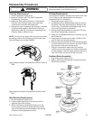
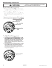
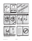
4. Install Stator by locating the dimple on the Stator, and
tightening the screw next to the dimple first.
5. Next tighten the screw 180 degrees across from the
dimple. Tighten remaining screws. Remove brake
tool.
6. Reinstall Drive Pulley, Cam, Washer, Retaining Ring,
and Dust Cap.
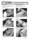
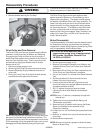
The Brake assembly, as well as the Snubber, is held in
position by the Brake Stator which is secured to the
underside of the Suspension Housing by six (6)
mounting screws.
Spring pressure forces the Rotor and Lining assembly
down on the Brake Stator and prevents the Transmission
from turning during agitation.
As stated previously, the Drive Pulley and Cams provide
a cam action which raises the Drive Pulley during the
counterclockwise (spin) direction of the Motor. When the
Dimple
Drive Pulley hub travels upward, it compresses the Brake
Spring and moves the Rotor and Lining assembly up the
drive tube disengaging it from the Stator. The Transmis-
sion is now free to spin.
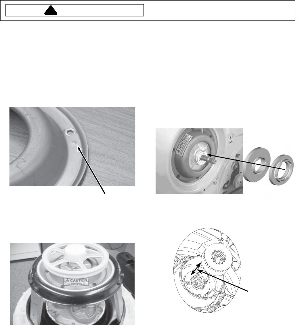
Splines in the Brake Rotor hub mesh with splines on the
drive tube end to provide positive vertical movement for
the Rotor and Lining assembly. The splines are greased
for ease of movement.
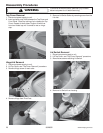
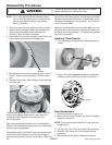
Installing Thrust Bearing
1. Thrust Bearing and Spacer are to be assembled as
shown.
2. Apply a thin layer of grease between the contacting
surfaces of the Lower Cam and the Drive Pulley.
Grease
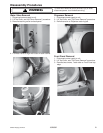
Base Replacement
1. Disconnect power supply to unit.
2. Remove Drain Pump and Belt, see “Drain Pump/Belt
Removal” procedure.
NOTE: There may be water remaining in the hose from
the last cycle.
3. Lift Top Cover, see “Top Cover Removal” procedure.
4. Remove Front Panel, see “Front Panel Removal”
procedure.
5. Remove Motor, see “Motor Removal” procedure.