


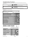
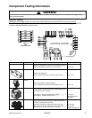
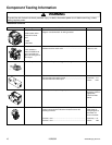
Component Testing Information
16 16026502 ©2005 Maytag Services
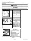
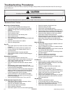
!
WARNING
To avoid the risk of electrical shock, personal injury, or death, disconnect power to unit before servicing, unless
testing requires power.
Mechanical Controls
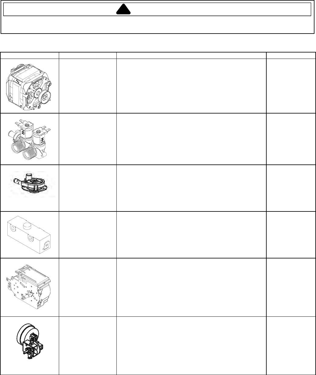
Illustration Component Test Procedure Results
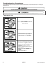
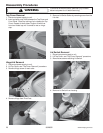
1 Speed Motor
CCW rotation when
viewed from shaft
end.
1/2HP
120V/60hz
Refer to Technical Data Sheet section “Internal Motor
Diagram” and “Schematic” for wiring contacts.
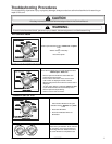
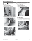
Water valve
120V 50/60hz, 5
watts Cold Side 2.25
gpm, Hot Side 2.00
gpm, Mix 3.00 gpm at
20-120 psi
Measure resistance of terminals on each valve.
Resistance across each valve.................................................
1000 Ω ± 10%
Drain Pump
Verify Drain Pump is not clogged or damaged.
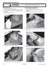
Lid Switch Disconnect wire terminals from switch.
Test terminals with switch closed..............................................
Test terminals with switch open. ..............................................
Continuity >1Ω
Infinite 1MΩ
Timer
Verify input and output voltage is present
.
Refer to timing
sequence chart on
appropriate
Technical Data
Sheet.
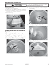
Pressure Switch Do not disconnect the pressure hose from pressure switch to
perform measurements. Measure resistance across the
following terminals.
Terminal 1 to 2................................................ .........................
Terminal 1 to 3..........................................................................
Refer to Technical
Data Sheet for
wiring diagram &
schematic for
correct contacts.
Continuity >1Ω
Infinite
1MΩ