


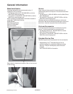
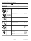
Component Testing Information
©2005 Maytag Services 16026502 15
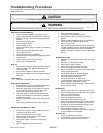
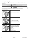
!
WARNING
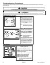
To avoid the risk of electrical shock, personal injury, or death, disconnect power to unit before servicing, unless
testing requires power.
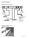
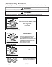
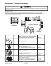
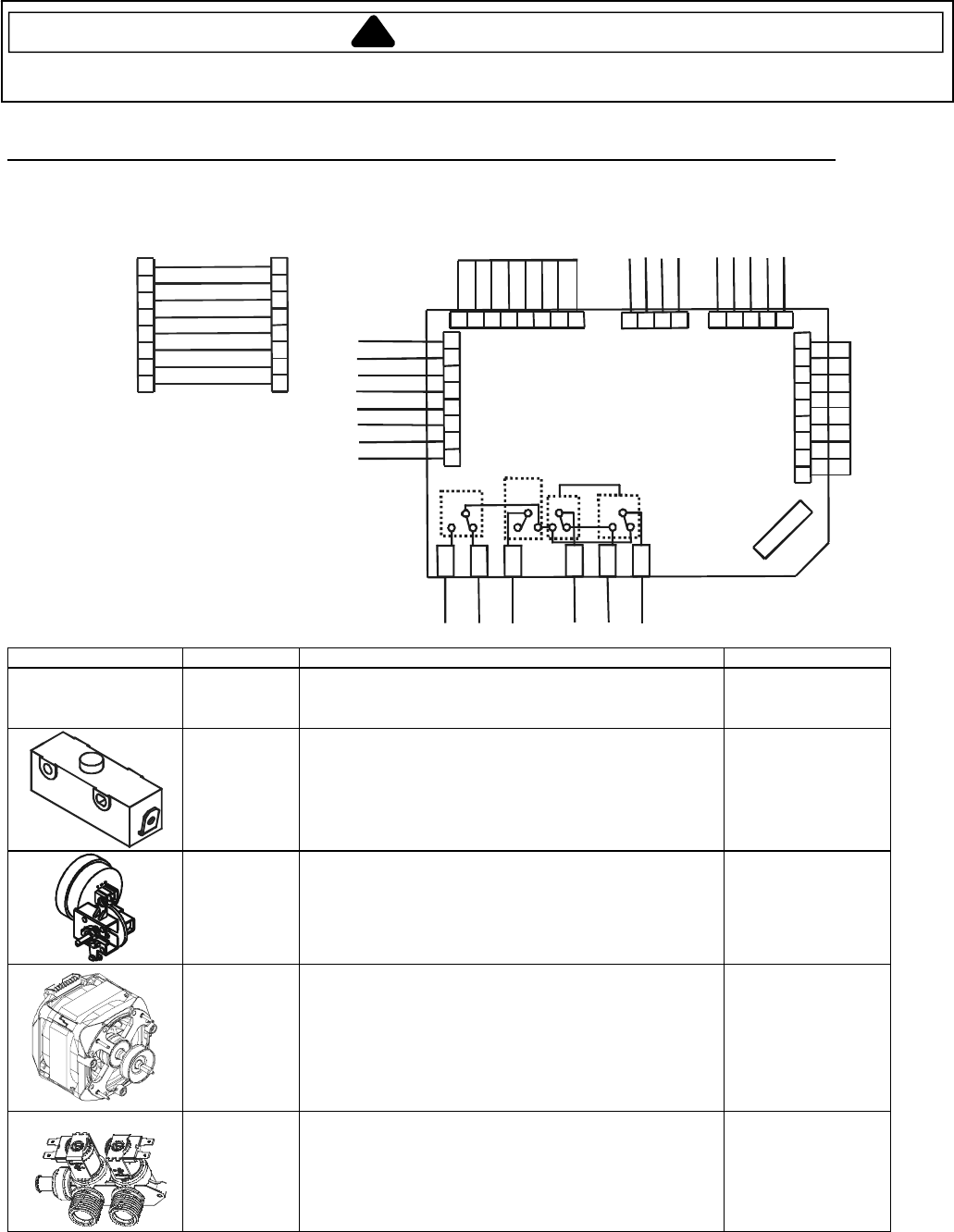
Electronic Controls
Resistance and voltage checks of components listed below can be made at PS5 on the control board.
Note: When making resistance checks on the components listed below, washer must be unplugged and PS5
connector disconnected from control board.
WH
BK
GY
PK
PU
YL
OR
GY
81
23
456
7
1
1
5
1
3
1
1
9
7
5
3
P
S
5
PS1
1234
PS6
B
K
B
U
P
U
B
R
12345
PS4
Y
L
/
R
D
W
H
/
Y
L
B
U
W
H
/
Y
L
R
D
/
B
K
8
1
23
456
7
PS2
9
P
S
3
P
S
9
P
S
1
0
P
S
1
1
P
S
1
2
P
S
7
P
S
8
B
R
G
Y
O
R
W
H
R
D
B
U
HI/LO
START
DIRECTION
R
E3R
E1
RE2
R
E0
CONTROL BOARD
PS5
E
X
P
O
R
T
W
A
S
H
E
R
D
O
M
E
S
T
I
C
W
A
S
H
E
R
1
1
3
1
1
9
7
3
1
7
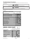
VIEW “A”
(EXPORT ONLY)
1
11
13
15
3
5
7
9
SPEED
1
5
WH
BK
GY
PK
PU
YL
OR
GY
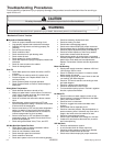
Illustration Component Test Procedure Results
AC Power
With the unit plugged in, check source voltage at Pin #15
WH and Pin #13 BK of PS5 on the control board...............
120 V AC
Lid Switch
With the unit plugged in,
check voltage at Pin #5 YL and Pin #15 WH of PS5..........
120 V AC
Pressure
Switch
With unit plugged in and the tub empty,
check voltage at Pin #3 OR and Pin #15 WH of PS5.........
120 V AC
Motor
Unplug washer, disconnect harness at PS5 and test from
wire insertion side of harness.
Run winding - PS7 GY and Pin #5 YL of PS5.....................
Start winding - PS9 BU and PS10 RD................................
1.5 ohms
4.0 ohms without
capacitor
Water Valves
Unplug washer, disconnect harness and test resistance
from wire insertion side of harness.
(Hot valve) Pin #9 PK of PS5 and Pin #3 OR of PS5..........
(Cold valve) Pin #7 PU of PS5 and Pin #3 OR of PS5........
(Thermistor) Pin #1 GY and Pin #11 GY of PS5.................
1120 ohms
1120 ohms
53000 ohms @ 70F