


29
Fabric Care Product Updates
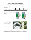
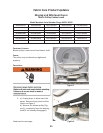
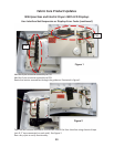
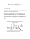
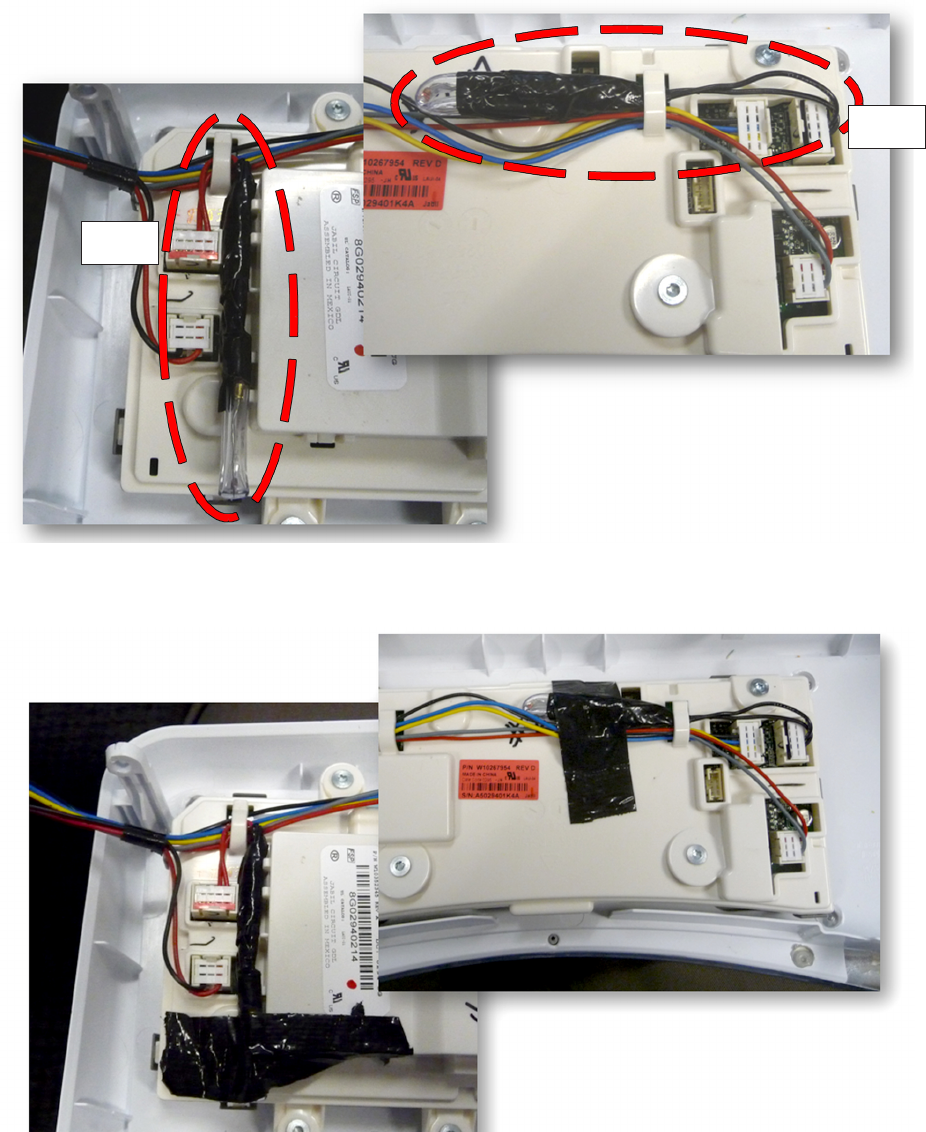
Add the 4-pin connector assembly to P12.
Add the 5-pin connector assembly to P03.
Route the resistor assemblies through the guides as illustrated in gure 1.
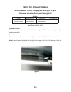
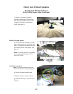
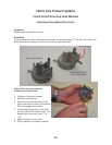
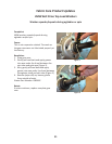
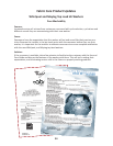
Tape the two resistor assemblies to the back side of the User Interface using electrical tape
(min 0.5” tape connected on each side). See gure 2.
Run a dry cycle to verify funconality.
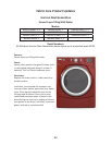
Whirlpool Gas and Electric Dryers With LCD Displays
User Interface Not Responsive or Displays Error Codes (connued)
Figure 1
Figure 2
P12
P03