


30 INSTALLATION AND MAINTENANCE MANUAL PUBLICATION DATE 03/02 504 766
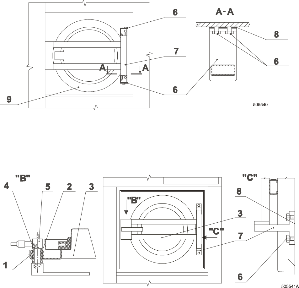
ADJUSTING ON THE SIDE OF THE DOOR HANDLE
ONLY FOR MACHINE 33/40/55 kg 80/100/125 lbs
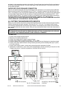
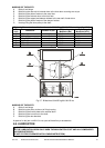
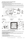
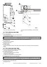
1. Unscrew the bolt (fig. 5.11.B, detail „B“, pos. 1) securing the casing of the door handle (2).
2. Unscrew the casing (2) from the door bearer (3) always by a whole turn that the groove in the casing
thread (2) appears bellow the securing bolt (1).
3. To make the casing turning (2) easier, use the semicircle notches (4) between the casing (2) and the
handle pin (5), in which you insert cylindrical object (a bolt etc.). By turning the handle, the casing (2) will
also move.
4. After the door thrust has been adjusted, tighten up the securing bolt (1) to the groove in the casing (2)
thread.
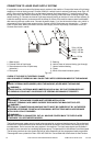
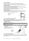
Fig.5.11.A Machines 22 kg / 50 lbs
1. Handle bolt
2. Handle sleeve
3. Door carrier beam
4. Semicircle cuts
5. Handle pin
6. Hinge bolt
7. Hinge
8. Elimination washer
9. Door
Fig.5.11.B Machines 33/40/55 kg 80/100/125 lbs
ADJUSTING ON THE SIDE OF THE DOOR HINGE
For machines 22kg / 50lbs (fig.5.11. A), and if the adjusting described above is not sufficient, for machines
33/40/55 kg 80/100/125 lbs (fig.5.11.B):
1. Loosen two bolts (6) fastening the top door hinge (7).
BE CAREFUL TO AVOID POSSIBLE FALLING OF THE DOOR WITH LOOSENED HINGE TO THE
FLOOR. RISK OF INJURIES!
2. Take off the elimination washer (8).
3. Tighten the two bolts (6) fastening the top door hinge.
4. Do the same with the bottom hinge.
5. Check if the door hinge has not moved, closing and opening of the door must be smooth.