


20 INSTALLATION AND MAINTENANCE MANUAL PUBLICATION DATE 03/02 504 766
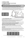
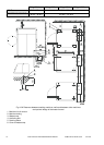
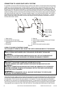
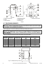
PROTECTION WITH EARTH LEAKAGE TRIPS
To increase the safety of the operating personnel and / or servicemen during the maintenance work
and operation with electric devices it is recommended to mount in front of the supply cable in the laundry
switchboard an earth leakage trip according to fig. 4.4.A, preferably with an actuating current 30 mA.
The main contacts of the earth leakage trip must comply with the specified power input of the machine.
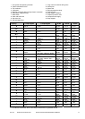
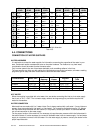
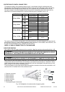
Specification of the earth leakage trip for individual machine types is illustrated in tab. 4.4.D.
Machine Voltage Heating type Max. current (A)
electric 18 kW 33,50
3AC
400V
steam 20,00
electric 18 kW 63,00
22 kg / 50 lbs
3AC
230V
steam 20,00
electric 24 kW 45,00
3AC
400V
steam 20,00
electric 24 kW 75,00
33 kg / 80 lbs
3AC
230V
steam 30,00
electric 36 kW 80,00
3AC
400V
steam 30,00
40 kg/ 100 lbs
3AC
230V
steam 40,00
electric 54 kW 92,00
3AC
400V
steam 30,00
55 kg / 125 lbs
3AC
230V
steam 40,00
Tab.4.4.D
The machine control circuits are supplied by a dividing transformer; the earth leakage trip is determined for
strong electric circuits i.e. motors, heating elements, motor contactors, circuit breaker, main switch etc., see
the inner connecting diagram list „A“ supplied with the machine.
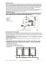
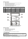
SUPPLY CABLE CONNECTION TO THE MACHINE
CABLE PREPARATION
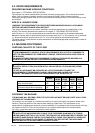
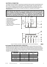
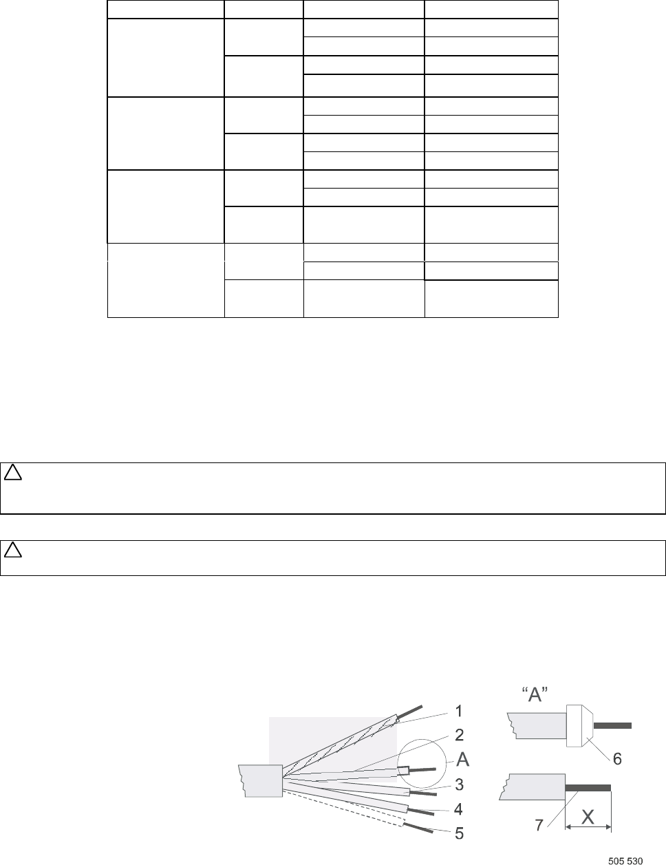
Use a cable or cord with copper conductors for the connection. Adapt the conductor ends according the fig. 4.4.B.
WARNING !
THE PROTECTIVE CONDUCTOR MUST BE LONGER SO THAT WHEN THE CABLE IS PULLED OUT
ACCIDENTALLY, THIS CONDUCTOR IS DISCONNECTED AS THE LAST ONE!
WARNING !
THE WASHER EXTRACTOR IS INTENDED TO BE PERMANENTLY CONNECTED TO FIXED WIRING.
When using the cable (hard copper conductors), strip individual cores in such way to avoid the protrusion of
a stripped part from the terminal when the conductor is connected into the device (6) - dimension X. When
using a cord (stranded copper conductors), the individual cores can be stripped in the same way as in the
case of a cable, or you can use moulded tubes (6).
To avoid a contact to a part under tension after the conductor connection even when the main switch is off,
use tubes with an insulated neck on the conductors ends.
1. Protection conductor
2. Phase conductor
3. Phase conductor
4. Phase conductor
5. Neutral conductor
6. Moulded tube
7. The stripped length of conductors
Fig. 4.4.B Adaptation of conductor ends of supplying cable
!
!