


504 766 PUBLICATION DATE 03/02 INSTALLATION AND MAINTENANCE MANUAL 15
4.2. SPACE REQUIREMENTS
REQUIRED MACHINE WORKING CONDITIONS:
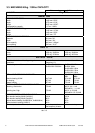
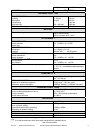
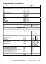
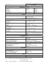
See chapter „3. TECHNICAL SPECIFICATION“.
The machine may not be installed within the reach of directly spraying water. Do not install the machine
where it will be exposed to weather condition and excessive humidity. When steamed up due to
temperature changing, water must not run over the machine walls and covers, nor to cover the floor under
and around it.
SIZE OF A LAUNDRY ROOM
IGNORING THE REQUIREMENT FOR SPACES BETWEEN MACHINES AND WALLS CAN MAKE
SERVICE AND MAINTENANCE WORK DIFFICULT.
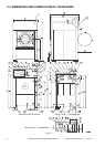
Total space requirements for the system installation are usually determinate by a detailed plan of the
building. The machine dimensions are stated in the chapter „3. TECHNICAL SPECIFICATION“.
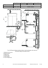
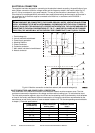
Leave at least 1 m / 3,3 ft of a space between the machine rear and the wall for the maintenance access.
Between the lateral sides of each machine leave a minimum space of 0,7 m / 2,3 ft (see fig. 4.3. A, dimension
„I“). Above the machine must be minimum 0,7 m / 2,3 ft of free space for the maintenance access.
The waste piping or outlet channel must be dimensioned to the discharged water quantity and a number of
washing machines.
4.3. MACHINE POSITIONING
CARRYING CAPACITY OF THE FLOOR
WARNING !
IT IS RECOMMENDED TO CONSULT STATIC REQUIREMENTS WITH A STATIC A ENGINEER TO
MEET THE REQUIREMENTS OF PERMISSIBLE LOADING, VIBRATIONS AND A NOISE LEVEL IN
THE BUILDING.
THE MANUFACTURER DOES NOT RECOMMEND TO INSTALL THE WASHING MACHINE IN A
ROOM WITH A CELLAR OR ON A FLOOR HAVING ROOMS BENEATH.
WARNING !
IN CASE OF INSTALLATION IN A ROOM WITH A CELLAR OR ON A FLOOR HAVING ROOMS
BENEATH:
THE INSTALLATION MUST BE APPROVED BY A STATIC ENGINEER TO MEET THE
REQUIREMENTS OF PERMISSIBLE LOADING, VIBRATIONS AND A NOISE LEVEL IN THE
BUILDING. THE MANUFACTURER IS NOT RESPONSIBLE FOR SUCH EFFECTS.
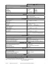
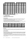
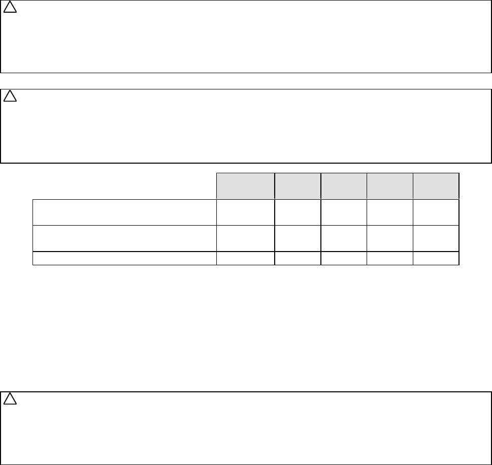
MODEL
22 kg
50 lbs
33 kg
80 lbs
40 kg
100 lbs
55 kg
125 lbs
Maximum static load of the floor
(with linen and water)
kg
lbs
831
1832
1597
3521
1746
3850
1951
4302
Maximum dinamic load of the floor
(alternative stress when extracting)
kg
lbs
±140
±309
±280
±617
±300
±662
±320
±706
Dynamic load frequency of the floor Hz 14,50 14,00 14,00 14,00
Tab. 4.3. A
FASTENING THE MACHINE
THE MACHINE WILL BE FIRMLY FIXED TO THE FLOOR AND MUST RELIABLY REST IN ALL FOUR
FOOTINGS OF THE MACHINE !
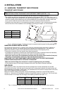
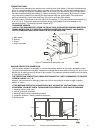
The machine is to be located on a levelled concrete floor to comply with static and dynamic stress of the
machine. Check the position of the machine base frame by a water level. The manufacturer is not
responsible for consequences caused by a wrong installation. It is expected to use anchoring bolts for fixing
the machine to the floor. There is also possible to use a suitable outlet channel for the waste water
(fig.4.3.A), unless the machine is connected to a drain pipeline.
WARNING !
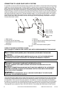
THE NUTS OF THE ANCHORING BOLTS HAVE TO BE TIGHTENED BY MEANS OF A TORQUE -
LIMITING RANGE (SEE TAB. 4.3.B). DO NOT TIGHTEN NUTS OF ANCHORING BOLTS BEFORE THE
CONCRETE BASE AROUND THE BOLTS IS COMPLETELY CURED. FOR CSA-NRTL/C APPROVED
MACHINES FOLLOWING IS APPLICABLE: TO REDUCE THE RISK OF FIRE, THIS APPLIANCE
MUST BE BOLTED TO AN UNCOVERED CONCRETE FLOOR.
!
!
!