


504 766 PUBLICATION DATE 03/02 INSTALLATION AND MAINTENANCE MANUAL 25
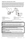
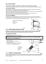
BEFORE REMOVING TOP OR BACK PANEL OF THE MACHINE, SWITCH POWER OFF AND WAIT
FOR AT LEAST 10 MINUTES. BEFORE STARTING INSPECTION OF FREQUENCY INVERTER,
CHECK FOR RESIDUAL VOLTAGE ACROSS MAIN CIRCUIT TERMINALS + AND -. THIS VOLTAGE
MUST BE BELOW 30VDC BEFORE YOU CAN ACCESS THE INVERTER FOR INSPECTION.
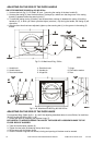
3. Clean and remove dirt and dust from:
– the cooling fin of the inverter
– the motor cooling fins
– the internal ventilator of the inverter (if present)
– the external ventilator (if present)
– the external air relieves of the machine
– check if ventilator in coolfins of inverter (if present) is functional
– check if external ventilator (if present) is functional
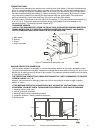
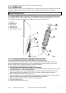
5.6. SAFETY VIBRATION SWITCH
FUNCTION DESCRIPTION
The vibration switch is an important safety element which must - if correctly adjusted - stop the machine if
excessive vibrations and shaking occur due to an unbalance caused by improper distribution of linen in the
washing drum. Because this component is very important, it is recommended that at the first installation and
then once in a year the vibration switch was verified by a qualified worker.
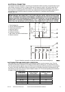
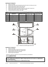
The unit contain the vibration switch (fig.5.6, pos.5) with a flexible controlling element which is attached to a
holder (7) by nuts (6) and this entire assembly is bolted to the bottom of the switchboard (4). The switch
controlling element is inserted into the rubber bushing (3) located into the limiter (2) which is bolted to the
drum front face (1). The switch attached to the switchboard is a part of the machine skeleton which is
attached to the frame and the limiter with the bushing is a part of the assembly that vibrates. The vibration
switch sensibility is given by a mutual adjusting of these two components which controls the unbalance level
of linen in the drum.
Reaction of the machine and the control system after the vibration switch is operated, has been described
in manuals „Programming manual - Electronic programmer“ or „Programming manual - Card programmer“.
VERIFYING OF THE FUNCTION
Perform the verifying as follows:
1. Open the control panel cover.
2. Start extraction mode.
3. After reaching of the maximum RPM, carefully switch over the vibration switch by moving the flexible
control element manually.
WARNING !
DO THIS CAREFULLY TO AVOID INJURIES BY VIBRATING AND FIRM PARTS OF THE MACHINE!
AFTER YOU HAVE CHECKED THE FUNCTION, MOUNT ALL PANEL COVERS BACK TO ORIGINAL PLACE !
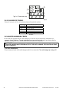
SENSIBILITY ADJUSTMENT
1. By moving the limiter (2) up or down, you will adjust the centre of rubber bushing to the control element
axis of vibration switch.
2. By moving the vibration switch on the holder (7) to the left, you will increase the sensibility and to the
right you decrease it. To reach the maximal permitted unbalance value it is necessary to keep the
distance of 100mm / 3,93“ between the limiter (2) and the vibration switch (5) - see the side view.
3. Moving the holder (7) with the switch left or right you will centre the switch control element in the rubber
bushing of the limiter.
!
!