


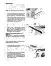
17
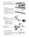
slot (A. Fig. 21), orient the guide tube (B) with
respect to the rail (C) as shown in Figure 21.
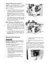
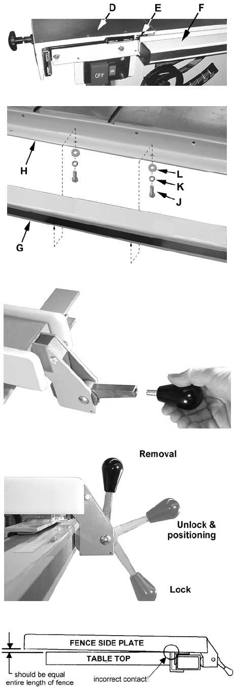
If your left table wing is the sliding table type
(D, Fig. 22), mount the guide tube (F) so it lines up
with the left edge on the angle iron portion of the
rail (E).
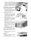
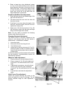
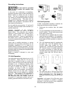
Referring to Figure 23:
1. Align the holes in the bottom of the guide
tube (G) with the holes in the front rail (H).
2. Fasten the guide tube (G) to the rail (H) from
beneath with 1/4-20 x 3/4 hex cap screws (J),
1/4 lock washers (K) and 1/4 flat washers (L).
Finger-tighten only.
3. Instructions for the installation of the scale on
the guide tube is given after the XACTA fence
has been assembled and given a preliminary
adjustment.
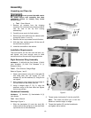
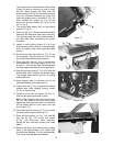
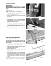
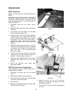
XACTA Fence
Screw the lock lever knob into the threaded handle
on the XACTA Fence II as shown in Figure 24.
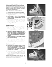
The lock lever has three functional positions as
shown in Figure 25:
• The upright position permits mounting and
removal of fence from the saw.
• The unlock position permits easy fence
positioning.
• The lower position locks the fence to the
front rail. The cam handle should be
pushed down firmly against the pin.
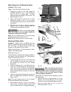
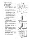
Fence Adjustments
Note: Fence adjustments should be performed in
the order given.
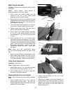
Level with the Saw Table Adjustment
1. Place the fence on the table and lock it.
2. View the fence from the left side of the saw.
Look for the space between the table and the
fence bottom to be equal along the entire
length of the fence (Figure 26).
3. If adjustment is necessary, unlock the fence.
Figure 22
Figure 23
Figure 24
Figure 25
Figure 26