


12
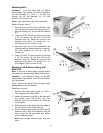
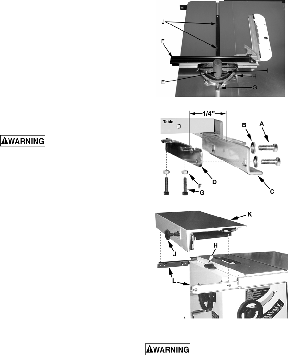
Miter Gauge for Left Extension Wing
Hardware: Miter Gauge
Tools: Cross Point Screw Driver, Square
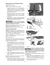
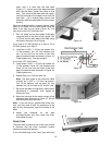
1. Change the angle on the miter gauge by
loosening handle (E, Fig. 7) and turning the
fence (F, Fig. 7) to desired angle. To move
gauge beyond index stops of 45° and 90°, flip
back the stop (G, Fig. 7).
2. Adjust index stops by turning one of three
adjustment screws (H, Fig. 7). Use a square
to verify that the fence is 90° to the saw blade,
see Figure 7.
3. Slide fence to the left, or right by loosening
handle (I, Fig. 7). Make sure fence does not
interfere with the blade when cutting.
The fence on the miter gauge
must not contact the saw blade! Failure to
comply may cause serious injury!
Note: You can adjust the play in the miter gauge
by tightening the set screws (J, Fig. 7).
Note: Always make test cuts to verify the angle.
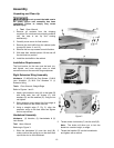
Mounting Sliding Table
Hardware: Sliding Table, (4) M8x25 Hex Cap
Screws, (4) M8 Hex Nuts, (8) M8 Flat Washers, (4)
M6 Hex Nuts, (4) M6x25 Socket Head Cap
Screws, (2) Flat Shims & (2) 90° Shims
Tools: Straight Edge, (2) 13mm Wrenches, 10mm
Wrench, 5mm Hex Wrench
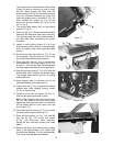
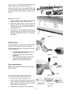
Referring to Figure 8:
The procedure for installing the leveling brackets is
the same for front rail and back rail. The illustration
(Figure 8) shows the front rail.
1. Thread two M6 hex nuts (F) all the way onto
the four M6x25 socket head cap screws (G)
and thread the screws into the leveling
bracket (D).
2. Place two washers (B) on two M8x25 hex cap
screws (A). Insert through the mounting slots
of the front rail (C) and secure to the threaded
holes of the leveling bracket (D). Position the
leveling bracket (D) to be about 1/4” from the
front rail (C).
3. Install the remaining leveling bracket onto the
back rail repeating the procedure outlined in
Steps 1 and 2.
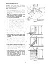
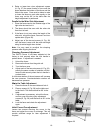
Note: The arbor pulley guard (H, Fig. 9) should
already be attached to the saw cabinet.
4. Mount table lock knob (J, Fig. 9) to the sliding
table (K, Fig. 9) with two M6x12 socket head
screws. Rotate knob 90° to engage/disengage
Figure 7
Figure 8
Figure 9
the lock.
Make sure that the lock knob is
in the locked position and that
the table is locked (does not slide on its support
plate). Failure to do so could result in injury
when attempting installation!
Read steps 5-7 carefully before attempting to mount
the sliding table.
5. Ensure that there is approximately a 1/4” gap
between rails and the brackets (C & D, Fig. 8)
so that you can set the sliding table in position.
6. Place the sliding table (K, Fig. 9) onto the
leveling brackets (L, Fig. 9).