


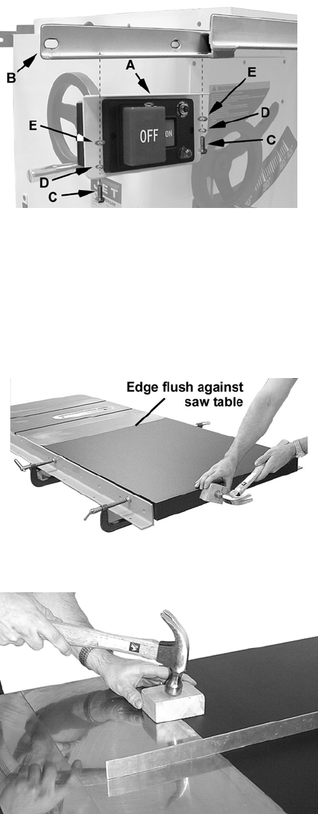
15
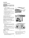
Mounting the Switch Assembly
Hardware: (2) 1/4x1/2 Hex Cap Screws,
(2) 1/4 Lock Washers, (2) 1/4 Flat Washers.
Tool: 4mm Hex Wrench
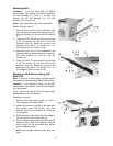
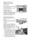
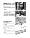
Referring to Figure 15:
Mount the switch assembly (A) to the bottom side
of the front rail (B) with two button head cap
screws (C) and two washers (D).
Note: The switch assembly can be installed in
various locations along the front rail.
On-Off Switch Padlock
Model No. BP-1, Stock No. 709736
To safeguard your machine from unauthorized
operation and to avoid accidental starting by young
children, the use of a padlock is highly
recommended. JET model BP-1 is available from
your local authorized JET distributor or by calling
JET Equipment & Tools at 800-274-6848.
Wooden Extension Table
The wooden extension table is an optional
accessory.
Hardware: (4) C-clamps
Tools: Electric drill, Cross point screwdriver, two
10mm wrenches, Straight edge, Hammer (or
rubber mallet)
Installation
The optional wood extension table (including the
optional router table) sits flush against the saw
table and along the inside of the rails. The JET
logo (or warning label on the router table) should
face outward. The extension table is not bolted to
the saw table, it is bolted only to the rails.
The extension table and saw table must be aligned
properly so the XACTA-FENCE II™ will slide
smoothly from one to the other.
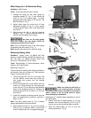
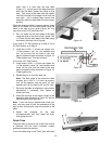
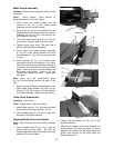
1. Place the extension table between the rails
and up against the saw table, leaving the
extension table raised just slightly above the
saw table. Clamp the extension table to the
front and back rails as shown in Figure 16.
Clamping pressure should be enough to
secure the table yet allow minor adjustments.
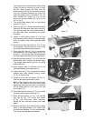
2. Use a hammer and block of wood (or a rubber
mallet) to tap the extension table up flush
against the cast iron saw table (Figure 16).
Then tap down the extension table at various
points along its edge where it meets the saw
Figure 15
Figure 16
Figure 17