


Installation
F232135
40
© Copyright, Alliance Laundry Systems LLC – DO NOT COPY or TRANSMIT
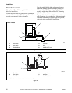
Drain Connection
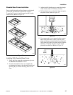
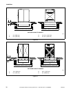
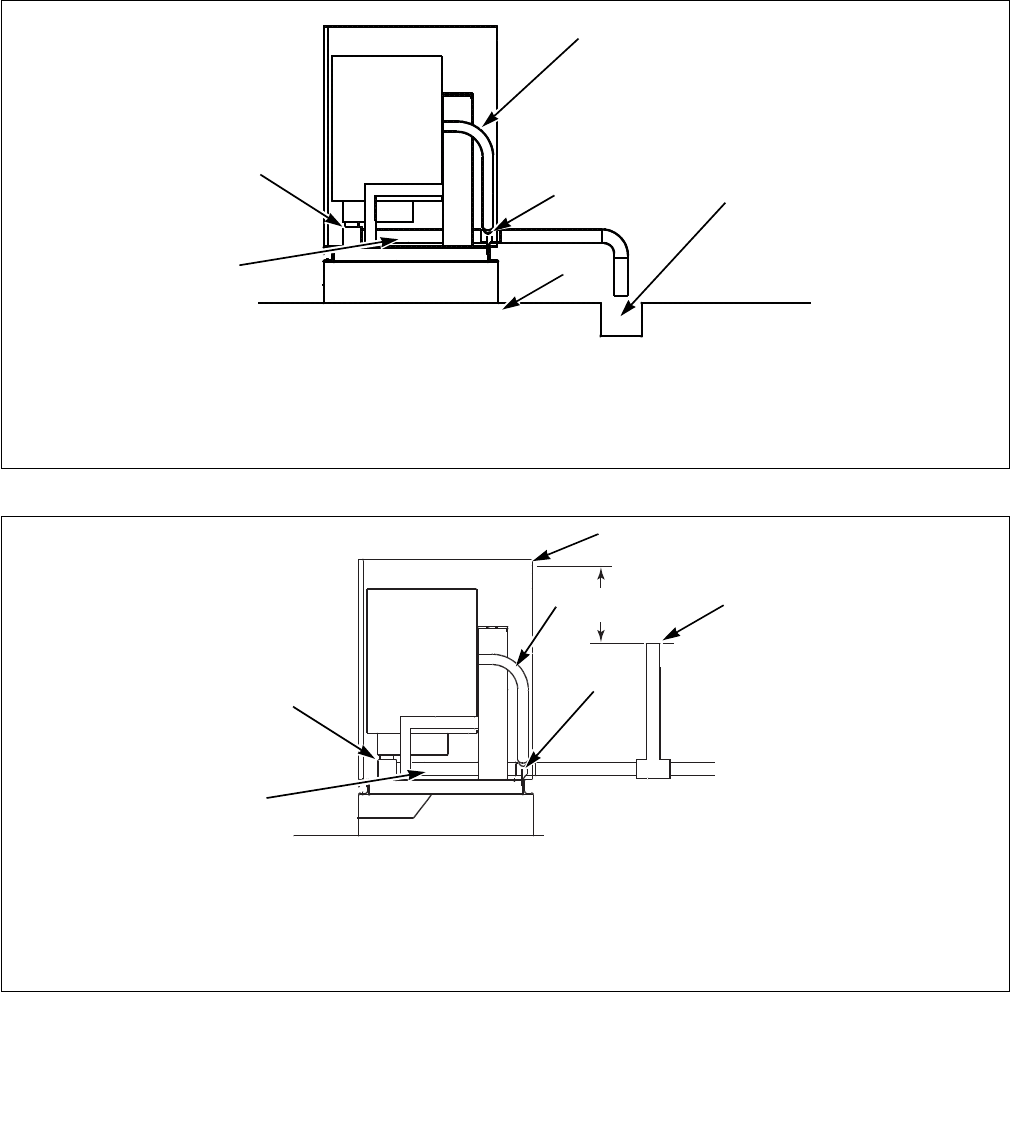
Figure 28 and Figure 29 show typical drain trough and
drain line installations.
Connect the drain outlet to a vented drain system using
only a flexible connection. The drain system must be
vented to prevent an air lock or siphoning.
Use the supplied black rubber adapter and clamps to
transition from the machine drain outlet to the two
inch schedule 40 PVC plumbing (20, 25 and 30
models) and the three inch schedule PVC plumbing
(40, 60 and 80 models).
If proper drain size is not available or practical, a surge
tank is required. A surge tank along with a sump pump
should be used when gravity drainage is not possible,
such as in below-ground-level installations.
Figure 28
Figure 29
H050I
1 Drain Hose 4 Drain Tee
2 Drain Valve 5 Floor
3 Overflow Hose 6 Open Drain Trough
H050I
1
2
3
4
5
6
DRAIN TROUGH
CHM2010N
1 Drain Hose 4 Overflow Hose
2 Drain Valve 5 Vent Pipe
3 Drain Tee 6 Water Inlet Valve*
* 1 foot (0.3 m) minimum between water inlet valve and vent pipe.
1
2
3
4
5*
1 ft.
(0.3 m)
DRAIN LINE
6*