


Installation
F232135
36
© Copyright, Alliance Laundry Systems LLC – DO NOT COPY or TRANSMIT
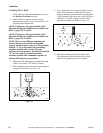
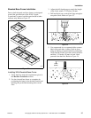
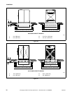
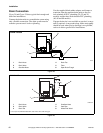
6. Raise and level the base frame 1/2 inch (13 mm)
off the floor on three points, using spacers such
as nut fasteners.
7. Fill the space between the frame base and the
floor with a good quality non-shrinking
machinery grout to ensure a stable installation.
Grout completely under all frame members.
8. Remove the spacers carefully, allowing the base
frame to settle into the wet grout.
9. Before grout sets completely, make a drain
opening in the rear of the base frame grouting
with a stiff piece of wire. This opening should be
approximately 1/2 inch (13 mm) wide to allow
any surface water build-up under the base of the
machine to drain away. Do not omit this step.
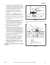
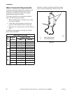
10. Position washers and locknuts on J-bolts and
fingertighten nuts to base frame.
11. After the grout is completely dry, tighten locknuts
by even increments – one after the other – until
all are tightened evenly and the base frame is
fastened securely to the floor. Refer to Figure 16.
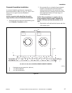
12. Position the machine over the base frame, aligning
the mounting holes on the machine with the
corresponding holes on the frame.
13. Install a bolt, lockwasher, and nut in each
mounting hole. Use 5/8 inch – 18 x 2
grade 5 mounting bolts with 5/8 inch – 18
grade B nuts and 5/8 inch lockwashers.
14. Handtighten each nut.
15. Tighten the two rear nuts two turns.
16. Tighten the two front nuts two turns.
17. On 25, 27, 30, 35, 40, 50 and 60 models, tighten
the two middle nuts firmly.
18. Tighten the two front nuts firmly; tighten the two
rear nuts firmly.
NOTE: Recheck the elevated base frame
installation one week after installation.