


Installation
35
F232135
© Copyright, Alliance Laundry Systems LLC – DO NOT COPY or TRANSMIT
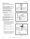
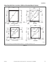
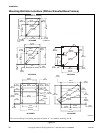
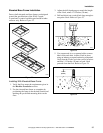
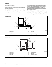
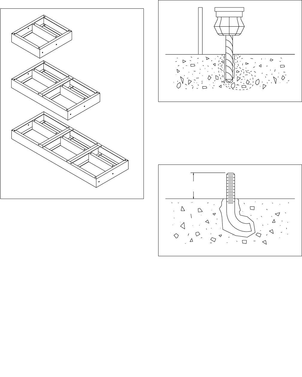
Elevated Base Frame Installation
Factory-built elevated steel base frames are designed
to meet the specifications of the 20-60 2 speed,
F speed and A-control variable-speed model washer-
extractor only. Refer to Figure 22.
Figure 22
Installing With Elevated Base Frame
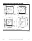
1. Verify the floor meets the requirements given in
the Machine Foundation section.
2. Use the elevated base frame as a template by
positioning the frame in the desired location and
marking the pre-drilled mounting holes on the
floor.
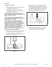
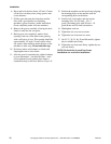
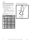
3. Adjust the drill depth gauge to match the length
of the J-bolt, minus 1-1/2 inches (38 mm).
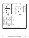
4. Drill and chisel out a conical hole large enough to
accept the J-bolt. Refer to Figure 23.
Figure 23
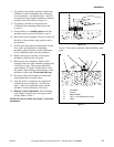
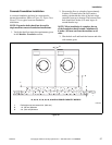
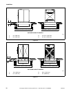
5. Use compressed air or a squeeze bulb to remove
debris from each hole. Anchor J-bolt in place,
using an industry-accepted anchoring compound.
Verify that the J-bolts are in the correct locations
and that 1-1/2 inches (38 mm) of each J-bolt
protrude from the floor. Refer to Figure 24.
Figure 24
H035I
H031I
H032I
H031I
H032I
1-1/2 in.
(38 mm)