


Installation
27
F232135
© Copyright, Alliance Laundry Systems LLC – DO NOT COPY or TRANSMIT
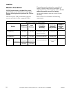
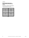
Machine Anchoring
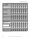
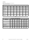
Before anchoring the machine, refer to Table 2 to
determine the appropriate method of anchoring for the
machine.
NOTE: Improper installation may void the
warranty. Consult the manufacturer or distributor
before varying from a procedure.
Direct-to-Finished-Floor Installation
Installing With Expansion Bolts
(2 Speed Models, Fixed-Speed and
A-Control Variable-Speed Models)
NOTE: Expansion bolts are not suitable VNV
machine installations.
1. Verify the floor meets the requirements given in
the Machine Foundation section.
2. Mounting surface should be level and machine
must be properly grouted.
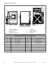
NOTE: If replacing a 35 pound machine with a
40 pound machine, note differences in cabinet size.
Refer to pages 20, 21 and 32.
NOTE: If replacing a 50 pound machine with a
60 pound machine, note differences in cabinet size.
Refer to pages 20, 21 and 32.
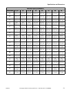
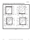
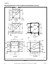
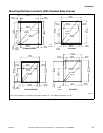
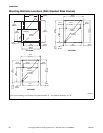
3. Use the base of the machine as a template by
positioning the machine in the desired location
and marking the pre-drilled mounting holes on
the floor. Metal templates are available at cost
through Alliance Laundry Systems. Refer to
Table 5 for ordering information.
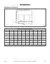
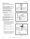
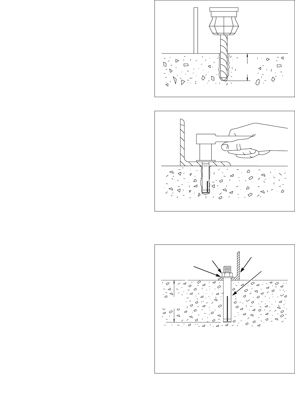
4. Set the drill depth gauge to 2-9/16 inches
(65 mm).
5. Drill the holes to the set depth. Refer to Figure
11.
6. Use compressed air or a squeeze bulb to clean out
each hole.
7. Install the machine anchors, using the included
tool.
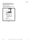
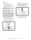
8. Secure the machine to the floor, using the bolts
furnished with the anchors. Tighten the locknuts
by even increments – one after the other – until
all are tightened evenly and the machine is
fastened securely to the floor. Refer to Figure 12.
Figure 11
Figure 12
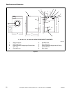
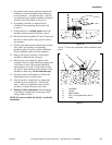
The completed expansion bolt installation is shown in
Figure 13.
Figure 13
U137I
H029I
CHM2032N
1 Washer
2 Locknut
3 Machine Base
4 5/8 in. (19 mm) Diameter Expansion Bolt
U137I
2-9/16 in.
(65 mm)
H029I
CHM203
2
2-9/16 in.
(65 mm)
1
4
3
2