


48 9001900
Section 3 Troubleshooting
© Copyright, Alliance Laundry Systems LLC – DO NOT COPY or TRANSMIT
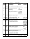
Brake transistor
alarm detection
If a brake transistor fault occurs due to excessively
large regenerative energy from the motor, for
example, that fault is detected to stop the inverter
output. In this case, the inverter power must be
switched off immediately.
Note: This function is activated only when the
optional brake resistor is connected.
Check for improper
braking duty.
• Change the inverter.
• Please contact your
sales representative.
Output side
ground fault
overcurrent
protection
This function stops the inverter output if a ground
fault overcurrent flows due to a ground fault which
occurred in the inverter's output (load) side. Use Pr.
249 "ground fault detection at start” to set whether
the protective function is to be activated or not. (In the
400V class, the protective function is always active.)
Check for a ground fault
in the motor and
connection cable.
Remedy the ground
fault portion.
External
thermal relay
operation
If the external thermal relay designed for motor
overheat protection or the internally mounted
temperature relay in the motor switches on (contacts
open), the inverter output is stopped. If the relay
contacts are reset automatically, the inverter will not
restart unless it is reset.
Note: This function is activated only when OH has
been set to any of Pr. 180 to Pr. 183 (input terminal
function selection).
• Check for motor
overheating.
• Check that the value of
7 (OH signal) is set
correctly in any of Pr.
180 to Pr. 183 (input
terminal function
selection).
Reduce the load and
operating duty.
Stall prevention The running frequency has fallen to 0 by stall
prevention activated. (OL while stall prevention is
being activated.)
Check the motor for use
under overload.
Reduce the load
weight.
Option alarm
Stops the
inverter output
if the inverter
station is
disconnected
from the system
in the NET
mode.
Also stops the inverter output if the dedicated option
used in the inverter results in setting error or
connection (connector) fault.
Note: Only when the FR-E5NC is fitted to the
three-phase 400V power input model.
Check that the plug-in
option connector is
plugged securely.
• Connect the plug-in
option securely.
• Please contact your
sales representative.
Parameter
storage device
alarm
A fault occurred in parameters stored (example:
E2PROM fault).
Check for too many
number of parameter
write times.
Please contact your
sales representative.
Parameter unit
disconnection
This function stops the inverter output if
communication between the inverter and PU is
suspended, e.g. the PU is disconnected, when "2",
"3", "16" or "17" was set in Pr. 75. This function stops
the inverter output if the number of successive
communication errors is greater than the number of
permissible retries when the Pr. 121 value is "9999"
for RS-485 communication from the PU connector.
• Check for loose fitting
of the control panel
(FR-PA02-o2) or
FR-PU04.
• Check the Pr. 75 setting.
Fit the control panel
(FR-PA02-o2) and
FR-PU04 securely.
Retry count
exceeded
If operation cannot be resumed properly within the
number of retries set, this function stops the inverter
output.
Find the cause of alarm
occurrence.
Eliminate the cause of
the error preceding this
error indication.
CPU error If the arithmetic operation of the built-in CPU does
not end within a predetermined period, the inverter
self-determines it as an alarm and stops the output.
Please contact your
sales representative.
CPU error This function stops the inverter output if a
communication error occurs in the built-in CPU.
(400V class only)
Please contact your
sales representative.
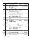
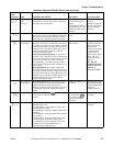
No Motor Operation With AC Drive Fault
(continued)
Operation
Panel
Indication Name Description and NOTES Check point Corrective action