


16
504524
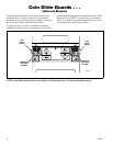
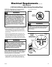
Electrical Requirements . . .
(Electric Dryers)
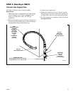
(120/240 Volt, 60 Hertz, 3-Wire Installation)
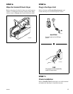
(120/208 Volt, 60 Hertz, 3-Wire Installation)
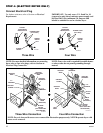
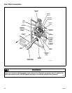
NOTE: The wiring diagram is located behind the
control panel, inside the control cabinet.
Grounding And Wiring Instructions
• Each dryer must be connected to a grounded metal,
permanent wiring system; or an equipment-grounding
conductor must be run with the circuit conductors and
connected to the equipment-grounding terminal or lead
on each dryer.
• Each dryer has its own terminal block that must be
connected to a separate branch, 60 Hertz, single phase
circuit, AC (alternating current) circuit, fused at 30
Amperes (the circuit must be fused on both sides of the
line). ELECTRICAL SERVICE FOR THE DRYER
UNIT SHOULD BE OF MAXIMUM RATED
VOLTAGE LISTED ON THE NAMEPLATE. DO
NOT CONNECT DRYER TO 110, 115, OR 120
VOLT CIRCUIT. Heating elements are available for
field installation in dryer units which are to be
connected to electrical service of different voltage than
that listed on nameplate, such as 208 Volt.
• If branch circuit to dryer unit is fifteen feet (4.50 m) or
less in length, use U.L. (Underwriters Laboratories)
listed No. 10 A.W.G. wire (copper wire only), or as
required by local codes. If over fifteen feet (4.50 m),
use U.L. (Underwriters Laboratories) listed No. 8
A.W.G. wire (copper wire only), or as required by local
codes. Allow sufficient slack in wiring so dryer can be
moved from its normal location when necessary.
• The power cord (pigtail) connection between wall
receptacle and dryer unit terminal block IS NOT
supplied with dryer unit. Type of pigtail and gauge of
wire must conform to local codes and with instructions
mentioned on the following pages.
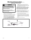
The method of wiring the dryer unit is optional and
subject to local code requirements. See examples below.
To reduce the risk of fire, electric shock or
personal injury, all wiring and grounding
MUST conform with the latest edition of the
National Electrical Code ANSI/NFPA 70 or the
Canadian Electrical Code, CSA C22.1, and
such local regulations as might apply. It is the
customer’s responsibility to have the wiring
and fuses checked by a qualified electrician
to make sure the laundry room has adequate
electrical power to operate the dryer.
W035
WARNING
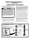
D003IE3A
POWER SUPPLY POWER SUPPLY
3-WIRE GROUNDED NEUTRAL
120/240 VOLT, 60 HERTZ AC 1 PHASE
SERVICE ENTRANCE SWITCH BOX
(SEE NOTE BELOW)
NEUTRAL WIRE NEUTRAL WIRE
METALLIC OR
NON-METALLIC
SHEATHED CABLE
(COPPER WIRE
ONLY)
PIGTAIL
TO DRYER
(SEE NOTE BELOW)
NEUTRAL
L1 L2
PIGTAIL CONNECTION
L1 L2
DIRECT CONNECTION
NEUTRAL
WALL
RECEPTACLE
INTERMEDIATE
FUSE BOX
(MAY BE
OMITTED IF
SERVICE
ENTRANCE
BOX IS FUSED)
INTERMEDIATE
SHUT-OFF BOX
(MAY OR MAY
NOT BE FUSED)
A typical
30-Amp
Three-wire
Receptacle
NEMA Type
10-30R
30 AMPERE FUSES OR
CIRCUIT BREAKER
TERMINAL BLOCK
IN DRYER
120 ± 12
VAC
240 ± 12
VAC
120 ± 12
VAC
NOTE: The power cord (pigtail) is NOT supplied with the
electric dryer. Type of pigtail and gauge of wire must conform
to local codes and instructions.
The method of wiring the dryer is optional and subject to local
code requirements.
NOTE: Connect the dryer to the power supply with the
MAXIMUM RATED VOLTAGE listed on the nameplate.
NOTE: Use COPPER WIRE only.
Shorter than 15' (4.5 m) use 10 A.W.G.
Longer than 15' (4.5 m) use 8 A.W.G.