


1-13
INSTALLATION
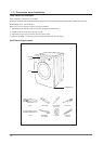
Parts and literature are packaged inside your dryer drum. To install:
1. Move your dryer to an appropriate location for installation. Consider installing the dryer and washer side-by-side, to allow access to
gas, electrical, and exhaust connections.
Lay two of the carton cushion-tops on the fl oor. Tip your dryer on its side so it will lay across both cushion-tops.
2. Set your dryer back in an upright position.
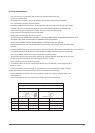
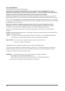
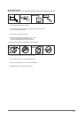
3. Review the Exhausting section before installing the exhaust system. Install the ductwork from your dryer to the exhaust hood. The
crimped end of the duct sections must point away from your dryer.
DO NOT use sheet metal screws when assembling ducting. These joints should be taped.
Never
use plastic fl exible exhaust material.
Tip for tight installations: install a section of exhaust system to your dryer before putting it in place.
Use duct tape to secure this section to your dryer, but do not cover louvers in dryer cabinet.
4. Review Electrical Requirements section.
BEFORE OPERATING OR TESTING, follow the grounding instructions in the Grounding section.
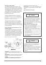
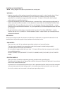
U.S. MODELS:
IMPORTANT – All U.S. models are produced for a 3-WIRE SYSTEM CONNECTION.
The dryer frame is grounded to the neutral conductor at the terminal block.
A 4-WIRE SYSTEM CONNECTION is required for new or remodeled construction, mobile homes,
or if local codes do not permit grounding through neutral. If the 4-wire system is used, the dryer frame cannot be grounded to the
neutral conductor at the terminal block. Refer to the following instructions for 3- and 4-WIRE SYSTEM CONNECTIONS.
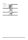
Remove the terminal block cover plate.
Insert the power cord with a UL-listed strain relief through the hole provided in the cabinet near the terminal block.
NOTE: A strain relief must be used.
Do not loosen the nuts already installed on the terminal block. Be sure they are tight.
Use a 3/8” (1cm) deep well socket.
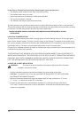
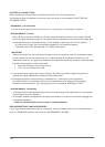
5. Review Gas Requirements section.
Remove the pipe thread protective cap.
Apply pipe joint compound or about 1 1/2 wraps of Tefl on tape over all threaded connections.
NOTE: Pipe joint compound must be resistant to the action of any liquefi ed petroleum gas.
Connect the gas supply to your dryer.
An additional fi tting is required to connect the 3/4” (1.9 cm) female thread end of a fl exible connector to the 3/8” (1 cm) male
threaded end on the dryer.
Securely tighten the gas line fi tting over threads.
Turn on the gas supply. Check all gas connections for leaks using a soap solution.
If bubbles appear, tighten the connections and recheck.
DO NOT use an open fl ame to check for gas leaks.