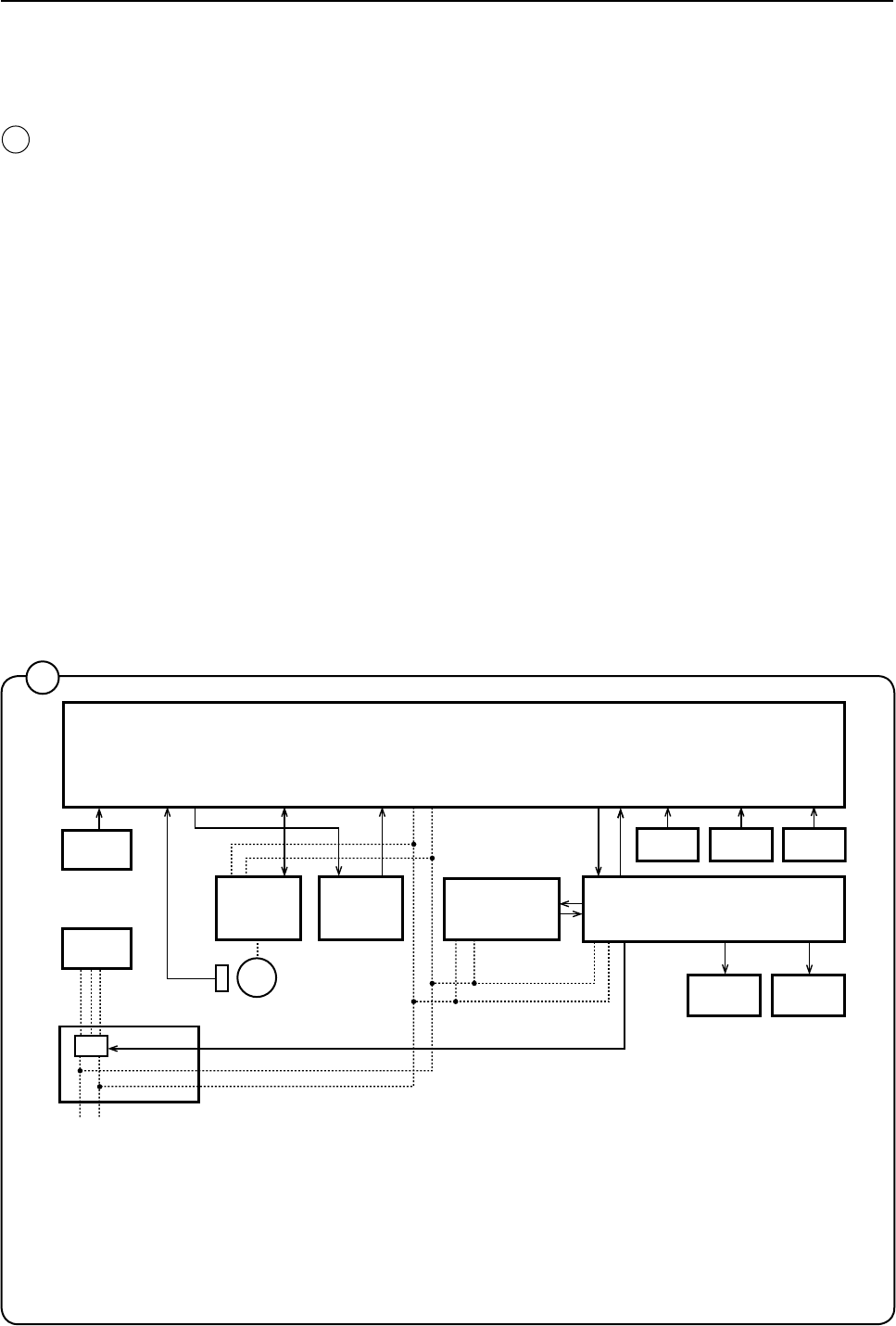
74
1
5
6
E1-E3
K21
14
8
7 9
10 11
M1
2
3
4
12
13
2
Door and door lock
Function
Thedoorlocklocksthedoor
Whenthedoorisclosed(closeddoorlockswitchS3),theprogrammeunit
mayrequestdoorlockingbyapplyingavoltageof200-240Vonthedoor
lockcontrollerA31inputX92.
ThefollowingcheckismadebytheA31cardpriortolockingofthedoor:
• No water in drum-input"level"fromlevelguardB2isclosed=0V
• Drum not turning-pulsefrequencyoninput"Tacho"fromrotation
sensorB3lessthan0.4Hz.
Whentheaboveconditionsaremet,thecardA1outputsaclosingpulse
onoutputD0tothedoorlockactuator/coil,whichthenlocksthedoor.The
microswitchesS4aandS4bintheactuator/doorlockareclosedwhenthe
doorislocked.Thesemicroswitchesfeedvoltageto:
• The output relays on the programme unit card. The relays control the
machine’sdrainandwatervalvesaswellasheaterswitch-on.
• Interlock signalformotorcontrol(inputX302)thatreleasesthemotor
start prevention state.
Programmeoperationisnowpossible.
2
1. ProgramunitA1
2. TemperaturesensorB1
3, LevelswitchB2
4, LevelswitchB4
5. DisplayA2
6. HeaterelementE1-3
7. MotorcontrolU1
8. RotationsensorB3
9. DoorlockmoduleA41
10. VoltageunitA5,PSU
11. I/Oboard
12. Watervalves
13. Drainvalve
14. Powersupply


