


63
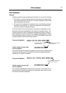
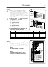
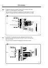
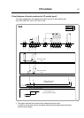
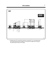
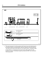
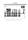
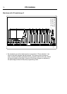
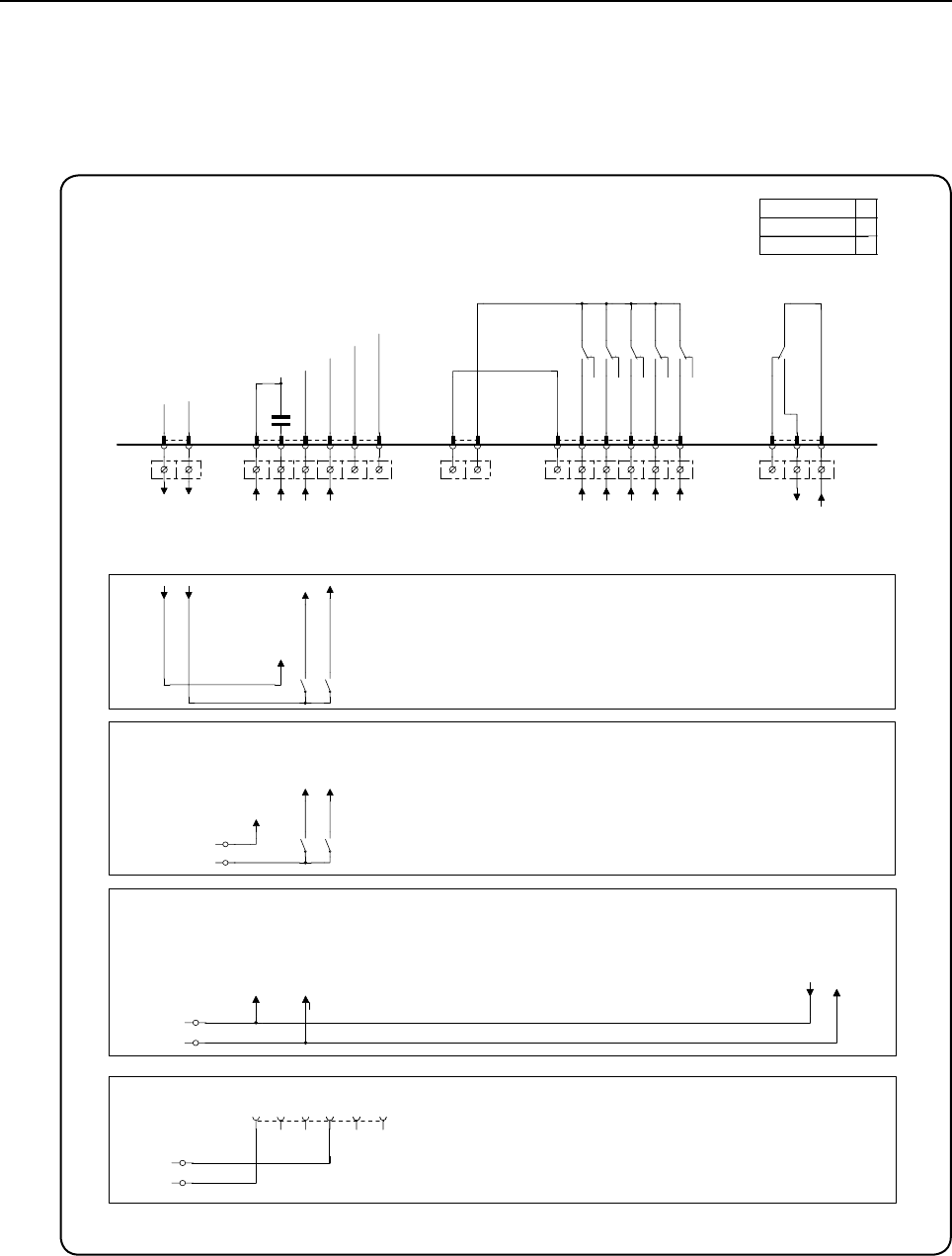
Circuit diagram of function options for I/O module type 2
ThewiringdiagramforI/Omoduletype2maybeoneofthefollowingvari-
ants:22A,22B,22C,22D,22E,22For22G.
I/O modules
1 2
P out
Con 111
1 2
N inputs
L inputs
3 4 5
Inp opt
Con 110
1 2 3 4 5 6
Common 24V
6 7 8 9 10
V in
Con 108
1 2
11 12 13
Out 5NO
Con 109
1 2 3 4 5 6
Liq 1
RE106
Liq 2
RE105
14 15 16
Liq 3
RE104
Liq 4
RE103
Liq 5
RE102
17 18 19
Out CO
Con 107
1 2 3
RE101
Prog. run
Address
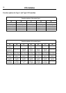
Function I/O:s
Type of I/O card
2
2
A
Coin 1
Price progr.
24V
230V
External Coin meter
-Common / .04 Common
0V
+24V
-Common 24V
-Coin 1
-Price progr.
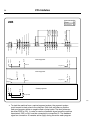
24V
External Coin meter
COMMON
+24V (switches to -24V when activating coin)
-24V (switches to +24V when activating coin)
-Common 24V
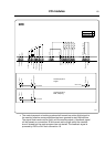
Central payment coin
-Prog. run
-Coin 1
-24V
Operation mode
+24V
-24V
Price programming mode
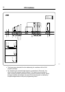
Central payment coin
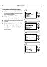
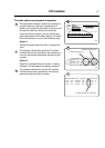
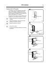
Connect the 6-pole connector marked
"Price" to the I/O-board
3 4 5 6 7 8
6606
22A
• Thesignalreceivedfromexternalslotmetersmustbeapulse.
In order to count down prices, the signal initiating the programming procedure
mustbeactive(high).