


ADE7753
–35–
REV. PrC 01/02
PRELIMINARY TECHNICAL DATA
Interrupt Status Register (0BH) / Reset Interrupt Status Register (0CH) /Interrupt Enable Register (0Ah)Interrupt Status Register (0BH) / Reset Interrupt Status Register (0CH) /Interrupt Enable Register (0Ah)
Interrupt Status Register (0BH) / Reset Interrupt Status Register (0CH) /Interrupt Enable Register (0Ah)Interrupt Status Register (0BH) / Reset Interrupt Status Register (0CH) /Interrupt Enable Register (0Ah)
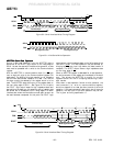
Interrupt Status Register (0BH) / Reset Interrupt Status Register (0CH) /Interrupt Enable Register (0Ah)
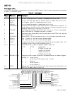
The Status Register is used by the MCU to determine the source of an interrupt request (IRQ). When an interrupt event occurs
in the ADE7753, the corresponding flag in the Interrupt Status register is set logic high. If the enable bit for this flag is logic
one in the Interrupt Enable register, the
IRQ logic output goes active low. When the MCU services the interrupt it must first
carry out a read from the Interrupt Status Register to determine the source of the interrupt.
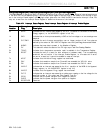
Table VII: Interrupt Status Register, Reset Interrupt Status Register & Interrupt Enable RegisterTable VII: Interrupt Status Register, Reset Interrupt Status Register & Interrupt Enable Register
Table VII: Interrupt Status Register, Reset Interrupt Status Register & Interrupt Enable RegisterTable VII: Interrupt Status Register, Reset Interrupt Status Register & Interrupt Enable Register
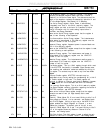
Table VII: Interrupt Status Register, Reset Interrupt Status Register & Interrupt Enable Register
BitBit
BitBit
Bit
InterruptInterrupt
InterruptInterrupt
Interrupt
LocationLocation
LocationLocation
Location
FlagFlag
FlagFlag
Flag
DescriptionDescription
DescriptionDescription
Description
0h AEHF Indicates that an interrupt was caused by the 0 to 1 transition of the MSB of the Active
Energy register (i.e. the AENERGY register is half full)
1h SAG Indicates that an interrupt was caused by a SAG on the line voltage or no zero crossings were
detected.
2h CYCEND Indicates the end of energy accumulation over an integer number of half line cycles as
defined by the content of the LINECYC Register—see Line Cycle Energy Accumulation Mode
3h WSMP Indicates that new data is present in the Waveform Register.
4h ZX This status bit reflects the status of the ZX logic ouput—see Zero Crossing Detection
5h TEMP Indicates that a temperature conversion result is available in the Temperature Register.
6h RESET Indicates the end of a reset (for both software or hardware reset). The corresponding
enable bit has no function in the Interrupt Enable Register, i.e. this status bit is set at
the end of a reset, but it cannot be enabled to cause an interrupt.
7h AEOF Indicates that the Active Energy register has overflowed.
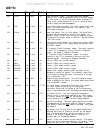
8h PKV Indicates that waveform sample from Channel2 has exceeded the VPKLVL value.
9h PKI Indicates that waveform sample from Channel1 has exceeded the IPKLVL value.
Ah VAEHF Indicates that an interrupt was caused by the 0 to 1 transition of the MSB of the Apparent
Energy register (i.e. the VAENERGY register is half full)
Bh VAEOF Indicates that the Apparent Enrgy register has overflowed.
Ch ZXTO Indicates that an interrupt was caused by a missing zero crossing on the line voltage for the
specified number of line cycles—see Zero Crossing Time Out
Dh PPOS Indicates that the power has gone from negative to positive.
Eh PNEG Indicates that the power has gone from positive to negative.
Fh RESERVED Reserved