


ADE7753
–13–
REV. PrC 01/02
PRELIMINARY TECHNICAL DATA
ADE7753 INTERRUPTSADE7753 INTERRUPTS
ADE7753 INTERRUPTSADE7753 INTERRUPTS
ADE7753 INTERRUPTS
ADE7753 Interrupts are managed through the Interrupt
Status register (STATUS[15:0]) and the Interrupt Enable
register (IRQEN[15:0]). When an interrupt event occurs in
the ADE7753, the corresponding flag in the Status register
is set to a logic one - see Interrupt Status register. If the enable
bit for this interrupt in the Interrupt Enable register is logic
one, then the
IRQ logic output goes active low. The flag bits
in the Status register are set irrespective of the state of the
enable bits.
In order to determine the source of the interrupt, the system
master (MCU) should perform a read from the Status
register with reset (RSTSTATUS[15:0]). This is achieved
by carrying out a read from address 0Ch. The
IRQ output will
go logic high on completion of the Interrupt Status register
read command—see Interrupt timing. When carrying out a read
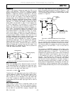
Therefore, writing 38h to the IPKLVL register will put the
channel 1 peak detection level at full scale and set the current
peak detection to its least sensitive value.
Writing 00h will put the channel 1 detection level at zero.
The detection is done when the content of the IPKLVL
register is smaller than the incoming channel 1 sample.
Peak Level RecordPeak Level Record
Peak Level RecordPeak Level Record
Peak Level Record
The ADE7753 records the maximum absolute value reached
by channel 1 and channel 2 in two different registers - IPEAK
and VPEAK respectively. VPEAK and IPEAK are 24-bit
unsigned registers. These registers are updated each time the
absolute value of the respective Waveform sample is above
the value stored in the VPEAK or IPEAK register. The
updated value corresponds to the last maximum absolute
value observed on the channel input. The RSTVPEAK and
RSTIPEAK registers also recorded the maximum absolute
value reached by channel 1 and channel 2 . RSTVPEAK and
RSTIPEAK registers value are respectively reset to zero
when the register is read.
IRQ
t
1
Jump to
ISR
Global int.
Mask Set
Clear MCU
int. flag
Read
Status with
Reset (05h)
ISR Action
(Based on Status contents)
ISR Return
Global int. Mask
Reset
t
2
t
3
MCU
int. flag set
Jump to
ISR
MCU Program
Sequence
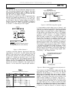
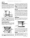
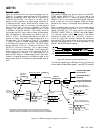
Figure 15– ADE7753 interrupt management
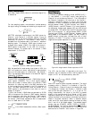
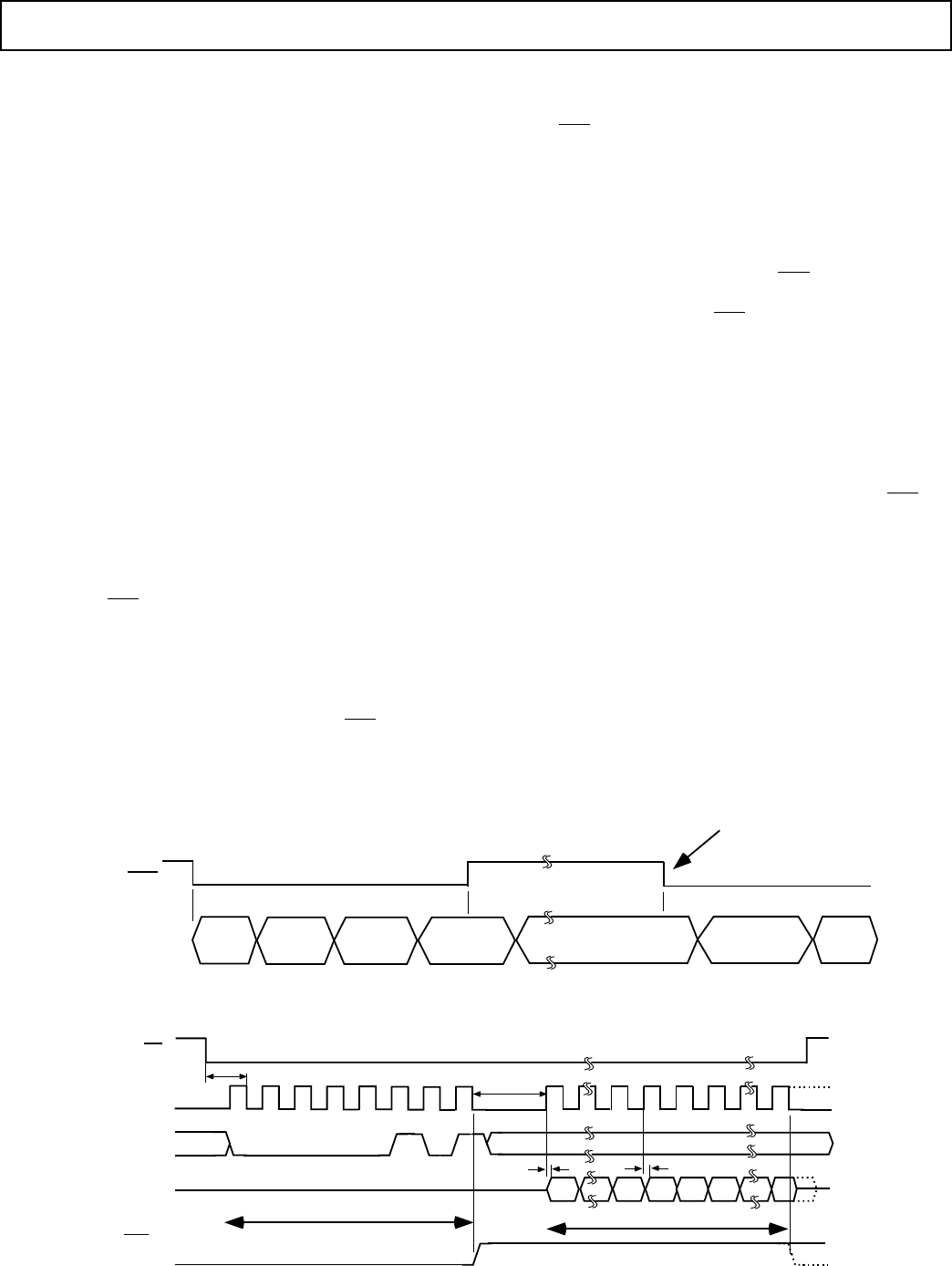
with reset, the ADE7753 is designed to ensure that no
interrupt events are missed. If an interrupt event occurs just
as the Status register is being read, the event will not be lost
and the
IRQ logic output is guaranteed to go high for the
duration of the Interrupt Status register data transfer before
going logic low again to indicate the pending interrupt. See
the next section for a more detailed description.
Using the ADE7753 Interrupts with an MCUUsing the ADE7753 Interrupts with an MCU
Using the ADE7753 Interrupts with an MCUUsing the ADE7753 Interrupts with an MCU
Using the ADE7753 Interrupts with an MCU
Shown in Figure 15 is a timing diagram which shows a
suggested implementation of ADE7753 interrupt manage-
ment using an MCU. At time t
1
the IRQ line will go active
low indicating that one or more interrupt events have oc-
curred in the ADE7753. The
IRQ logic output should be tied
to a negative edge triggered external interrupt on the MCU.
On detection of the negative edge, the MCU should be
configured to start executing its Interrupt Service Routine
(ISR). On entering the ISR, all interrupts should be disabled
using the global interrupt enable bit. At this point the MCU
external interrupt flag can be cleared in order to capture
interrupt events which occur during the current ISR. When
the MCU interrupt flag is cleared a read from the Status
register with reset is carried out. This will cause the
IRQ line
to be reset logic high (t
2
)—see Interrupt timing. The Status
register contents are used to determine the source of the
interrupt(s) and hence the appropriate action to be taken. If
a subsequent interrupt event occurs during the ISR, that event
will be recorded by the MCU external interrupt flag being set
again (t
3
). On returning from the ISR, the global interrupt
mask will be cleared (same instruction cycle) and the external
interrupt flag will cause the MCU to jump to its ISR once
again. This will ensure that the MCU does not miss any
external interrupts.
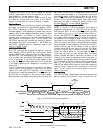
Interrupt timingInterrupt timing
Interrupt timingInterrupt timing
Interrupt timing
The ADE7753 Serial Interface section should be reviewed first
before reviewing the interrupt timing. As previously de-
CS
SCLK
DIN
t
1
t
11
t
11
t
9
DB7
DOUT
DB0
DB0
DB7
000
Read Status Register Command
0
1
0
0
1
IRQ
Status Register Contents
Figure 16– ADE7753 interrupt timing