


ADE7753
–27–
REV. PrC 01/02
PRELIMINARY TECHNICAL DATA
CALIBRATING THE ENERGY METERCALIBRATING THE ENERGY METER
CALIBRATING THE ENERGY METERCALIBRATING THE ENERGY METER
CALIBRATING THE ENERGY METER
Calculating the Average Active PowerCalculating the Average Active Power
Calculating the Average Active PowerCalculating the Average Active Power
Calculating the Average Active Power
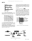
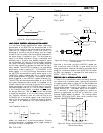
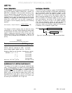
When calibrating the ADE7753, the first step is to calibrate
the frequency on CF to some required meter constant, e.g.,
3200 imp/kWh.
In order to determine the output frequency on CF, the
average value of the Active Power signal (output of LPF2)
must first be determined. One convenient way to do this is to
use the line cycle energy accumulation mode. When the
CYCMODE (bit 7) bit in the Mode register is set to a logic
one, energy is accumulated over an integer number of half
line cycles as described in the last section.
Since the line frequency is fixed at, say 60Hz, and the number
of half cycles of integration is specified, the total integration
time is given as :
cycleshalfofno
Hz
.
602
1
×
×
For 255 half cycles this would give a total integration time of
2.125 seconds. This would mean the energy register was
updated 2.125 / 1.1175µs (4/CLKIN) times. The average
output value of LPF2 is given as :
updatedwasLEAENERGYtimesofNumber
endtheatLAENERGYofContent
Or equivalently, in terms of contents of various ADE7753
registers and CLKIN and line frequencies (fl):
CLKINLINECYC
flLAENERGY
LPFWordAverage
×
××
=
]0:15[
8
)2(
(24)
where f
l
is the line frequency.
Calibrating the Frequency at CFCalibrating the Frequency at CF
Calibrating the Frequency at CFCalibrating the Frequency at CF
Calibrating the Frequency at CF
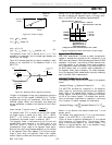
Once the average Active Power signal is calculated it can be
used to determine the frequency at CF before calibration.
When the frequency before calibration is known, the pair of
CF Frequency Divider registers (CFNUM and CFDEN)
can be adjusted so as to produce the required frequency on
CF. In this example a meter constant of 3200 imp/kWh is
chosen as an appropriate constant. This means that under a
steady load of 1kW, the output frequency on CF would be,
Hz
kWhimp
CFFrequency
8888.0
3600
3200
sec60min60
/3200
)(
==
×
=
Assuming the meter is set up with a test current (basic
current) of 20A and a line voltage of 220V for calibration, the
load is calculated as 220V × 20A = 4.4kW. Therefore the
expected output frequency on CF under this steady load
condition would be 4.4 × 0.8888Hz = 3.9111Hz.
Under these load conditions the transducers on Channel 1
and Channel 2 should be selected such that the signal on the
voltage channel should see approximately half scale and the
signal on the current channel about 1/8 of full scale (assuming
a maximum current of 80A). The average value from LPF2
is calculated as 52,428.81 decimal using the calibration
mode as described above. Then using Digital to Frequency
Conversion, the frequency under this load is calculated as:
Hz.
MHz..
)CF(Frequency
566349
2
57954538152428
29
=
´
=
This is the frequency with the contents of the CFNUM and
CFDEN registers equal to 000h. The desired frequency out
is 3.9111Hz. Therefore, the CF frequency must be divided
by 349.566/3.9111Hz or 89.3779 decimal. This is achieved
by loading the pair of CF Divider registers with the closest
rational number. In this case, the closest rational number is
found to be 25/2234 (or 19h/8BAh). Therefore, 18h and
8B9h should be written to the CFNUM and CFDEN
registers respectively. Note that the CF frequency is divided
by the contents of (CFNUM + 1) / (CFDEN + 1). With the
CF Divide registers contents equal to 18h/8B9h, the output
frequency is given as 349.566Hz / 89.36 = 3.91188Hz. This
setting has an error of +0.02%.
Calibrating CF is made easy by using the Calibration mode
on the ADE7753. The only critical part of the set up is that
the line frequency be exactly known. If this is not possible if
could be measured by using the ZX output of the ADE7753.
Note that changing WGAIN[11:0] register will also affect
the output frequency from CF. The WGAIN register has a
gain adjustment of 0.0244% / LSB.
Energy Meter DisplayEnergy Meter Display
Energy Meter DisplayEnergy Meter Display
Energy Meter Display
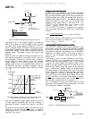
Besides the pulse output which is used to verify calibration,
a solid state energy meter will very often require some form
of display. The display should display the amount of energy
consumed in kWh (Kilo-Watt Hours). One convenient and
simple way to interface the ADE7753 to a display or energy
register (e.g., MCU with nonvolatile memory) is to use CF.
For example the CF frequency could be calibrated to 1,000
imp/kWhr. The MCU would count pulses from CF. Every
pulse would be equivalent to 1 watt-hour. If more resolution
is required the CF frequency could be set to, say 10,000 imp/
kWh.
If more flexibility is required when monitoring energy usage
the Active Energy register (AENERGY) can be used to
calculate energy. A full description of this register can be
found in the Energy Calculation section. The AENERGY reg-
ister gives the user both sign and magnitude information
regarding energy consumption. On completion of the CF
frequency output calibration, i.e., after the Active Power
Gain (APGAIN) register has been adjusted a second calibra-
tion sequence can be initiated. The purpose of this second
calibration routine is to determine a kWh/LSB coefficient for
the AENERGY register. Once the coefficient has been
calculated the MCU can determine the energy consumption
at any time by reading the AENERGY contents and multiply-
ing by the coefficient to calculate kWh.