


ADE7753
–10–
REV. PrC 01/02
PRELIMINARY TECHNICAL DATA
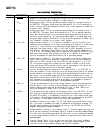
Waveform register will give an indication of the offset in the
channel. This offset can be canceled by writing an equal and
opposite offset value to the relevant offset register. The offset
correction can be confirmed by performing another read.
Note when adjusting the offset of Channel 1, one should
disable the digital integrator and the HPF.
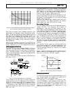
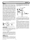
CH1OS[5:0]
00h
1Fh
3Fh
+50mV
-50mV
0mV
Offset
Adjust
01, 1111b
11, 1111b
Sign + 5 Bits
Sign + 5 Bits
Figure 4– Channel Offset Correction Range (Gain = 1)
GainGain
GainGain
Gain
Correctable SpanCorrectable Span
Correctable SpanCorrectable Span
Correctable Span
LSB SizeLSB Size
LSB SizeLSB Size
LSB Size
1 ±50mV 1.61mV/LSB
2 ±37mV 1.19mV/LSB
4 ±30mV 0.97mV/LSB
8 ±26mV 0.84mV/LSB
16 ±24mV 0.77mV/LSB
Table IITable II
Table IITable II
Table II
Offset Correction range
di/dtdi/dt
di/dtdi/dt
di/dt
CURRENT SENSOR AND DIGITAL INTEGRATOR CURRENT SENSOR AND DIGITAL INTEGRATOR
CURRENT SENSOR AND DIGITAL INTEGRATOR CURRENT SENSOR AND DIGITAL INTEGRATOR
CURRENT SENSOR AND DIGITAL INTEGRATOR
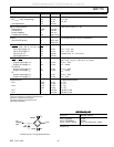
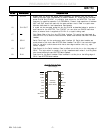
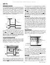
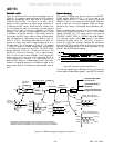
di/dt sensor detects changes in magetic field caused by ac
current. Figure 5 shows the principle of a di/dt current
sensor.
+
-
EMF (electromotive force)
induced by changes in
magnetic flux density (d/dt)
Magnetic field created by current
(directly proportional to current)
Figure 5– Principle of a di/dt current sensor
The flux density of a magnetic field induced by a current is
directly proportional to the magnitude of the current. The
changes in the magnetic flux density passing through a
conductor loop generates an electromotive force (EMF)
between the two ends of the loop. The EMF is a voltage signal
which is proportional to the di/dt of the current. The voltage
output from the di/dt current sensor is determined by the
mutual inductance between the current carrying conductor
and the di/dt sensor.
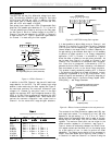
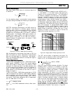
The current signal needs to be recovered from the di/dt signal
before it can be used. An integrator is therefore necessary to
restore the signal to its original form. The ADE7753 has a
built-in digital integrator to recover the current signal from
the di/dt sensor. The digital integrator on Channel 1 is
switched on by default when the ADE7753 is powered up.
Setting the MSB of CH1OS register will turn on the
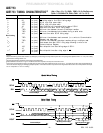
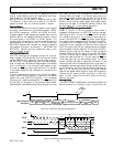
integrator. Figures 6 to 9 show the magnitude and phase
response of the digital integrator.
10
1
10
2
10
3
10
4
-60
-50
-40
-30
-20
-10
0
10
20
30
FREQUENCY-Hz
GAIN-dB
Figure 6– Combined gain response of the digital integrator
and phase compensator
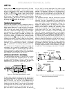
10
1
10
2
10
3
10
4
-92
-91.5
-91
-90.5
-90
-89.5
-89
-88.5
-88
FREQUENCY-Hz
PHASE-DEGREES
Figure 7– Combined phase response of the digital integra-
tor and phase compensator
40 45 50 55 60 65 70
-6
-5
-4
-3
-2
-1
0
FREQUENCY-Hz
GAIN-dB
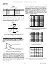
Figure 8– Combined gain response of the digital integrator
and phase compensator (40Hz to 70Hz)