


113068-7 www.amdry.com 43
(2) The pilot line contains a back-loaded pressure regulator with an impulse line connected to
the gas burner inlet. The regulator will maintain a constant pilot supply pressure in the
burner due to an increase in temperature. DO NOT adjust this regulator.
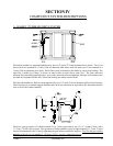
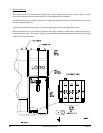
6) Main Gas Supply Line
The main gas supply line consists of a pressure regulator, two (2) motorized shutoff valves, Hi/Lo
gas pressure switch, main gas valve proof of closure switch, and manual shutoff valve.
The gas pressure at the burner should be 2.5 inches (6.22 mb) of water column (W.C.) for natural
gas and 1.25 inches (3.1 mb) of water column (W.C.) for liquid propane (L.P.) gas. This pressure
is measured by a manometer at the pressure tap, which is located above the top manual shutoff
valve.
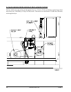
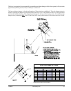
a) Motorized Gas Valve
The two (2) 2” F.P.T. motorized valves are “ON/OFF” gas flow control valves. The valves
motors operate on 120 VAC and are electrically “cascaded” so that upper valve will not open
until lower valve has fully opened. A limit switch inside the lower motorized valve provides the
signal that the valve is fully opened. These valves will open only when the burner controller
module (BCM) is receiving a signal from the flame rod proving that the pilot flame is established.
b) Top Motorized Gas Valve
The valve sets the gas rate of 2,800,000 Btu/hr (705,588 kcal/hr). To achieve this rate, the
pressure must be set for 2.5 inches (6.22 mb) of water column (W.C.) for natural gas and 1.25
inches (3.1 mb) of water column (W.C.) for L.P. gas. To adjust, loosen the pan head screw
located on the front of the top motorized valve, while holding the valve body, turn the flow
adjustment clockwise (CW) for less gas and counterclockwise (CCW) for more gas. Retighten
the pan head screw when correct gas flow is achieved. There is a switch located on the back
of the top gas valve that verifies valve closure. The BCM will go into a system unsafe error and
the burner will not begin a burner sequence.
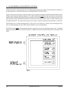
c) Sequence of Operation
With dryer power on, a 120 volt signal is sent to terminal #1 and terminal #2 of the BCM. A
power indicator light has been added to the controller base for troubleshooting.
(1) Drying cycle is started.
(2) Dryer computer calls for heat.
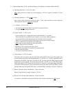
(3) The BCM checks that ALL of the dryer’s safety circuits are closed (terminal #7 of the
BCM). If this is the case, then the “green” “operating interlocks” light emitting diode
(L.E.D.) on the BCM will light. If a safety switch is open, the “green” L.E.D. will not
light, and the “red” “SYSTEM UNSAFE” L.E.D. will light. The ignition sequence will
stop.