


8 American Dryer Corp. 113068-7
SECTION III
INSTALLATION PROCEDURES
Installation should be performed by competent technicians in accordance with local and state codes. In the
absence of these codes, the installation must conform to applicable American National Standards: ANSI Z223.1-
LATEST EDITION (National Fuel Gas Code) or ANSI/NFPA NO. 70-LATEST EDITION (National Electrical
Code) or in Canada, the installation must conform to applicable Canadian Standards: CAN/CGA-B149.1-M91
(Natural Gas) or CAN/CGA-B149.2-M91 (Liquid Propane [L.P.] Gas) or LATEST EDITION (for General
Installation and Gas Plumbing) or Canadian Electrical Codes Parts 1 & 2 CSA C22.1-1990 or LATEST EDITION
(for Electrical Connections).
A. REASSEMBLY OF DRYER
IMPORTANT: Always keep the basket (tumbler) section of the dryer in an upright position when
moving it.
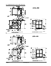
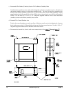
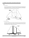
1. Reassembly Instructions for Dryer Shipped in Two (2) Pieces
In this method of shipment, the basket (tumbler) section and the basket (tumbler) base section are shipped
as one (1) unit and the heat console section is the second.
a. Reassemble Basket (tumbler) and Basket (tumbler) Base Section To The Heat Console Section
Move both pieces into position by lifting them with cables through the eyebolts located at the top of each
of the two (2) sections. These pieces may also be moved into place with a forklift truck by lifting the
pieces from underneath. The basket (tumbler) and basket (tumbler) base section weighs about 6,400
pounds (2,903 kg) and the heat console section weighs about 4,100 lb (1,860 kg). Once the sections are
in position, the seven (7) clearance holes on the basket (tumbler) base section (four [4] in the front and
three [3] in the rear) must be aligned with the seven (7) 3/8-16 tapped holes in the heat console section.
Use the three (3) #8-16 x 2” long bolts along with the tapered shims supplied to bolt the two (2) sections
together.
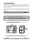
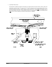
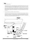
b. Reattach The Optional Control Pendant Arm
Position the control pendant arm to the top front of the heat console section by aligning the clearance
holes in the arm with the 1/4-20 tapped holes on the top of the heat console section. Use the 1/4-20 x
3” long bolts supplied with the dryer to attach the arm to the console.
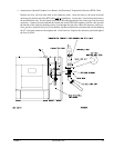
c. Reconnect the internal air, electric, and water connections (refer to page 12 through page 17).