


42 American Dryer Corp. 113068-7
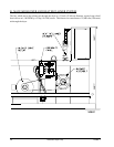
a) Burner Fan Air Switch
The differential in air pressure is measured by the burner fan air switch, which is located next to
the burner fan motor. If the combustion air is inadequate, this switch will prevent ignition. The
setting of this switch is adjustable, and it should be set at 12 to 15 millimeters (0.4-0.6 inches
[0.995-1.49 mb] of water column [W.C.]).
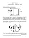
b) Burner Fan and Motor
The combustion air is produced by a 6-1/4” (15.88 cm) squirrel cage fan, which is attached to a
1-1/2 hp (1.12 kW), 3,600 rpm motor. The motor must spin counterclockwise (CCW) as viewed
from the rear of the motor.
c) Combustion Air Lint Filter
The combustion air lint filter is made of a fine mesh stainless steel screen, which must be
cleaned regularly. This screen prevents any lint from entering the burner box.
d) Sail Switch
The sail switch is located in the rear left hand corner of the dryer closest to the lint drawer. A
sail switch consists of a round damper plate on a lever arm, which is in contact with an electric
switch. When the air blower comes on, it draws air through the lint drawers. This creates a
negative pressure inside the dryer. This negative pressure pulls in the sail switches. If the sail
switches DO NOT pull in, this will prevent the heat circuit from energizing and the computer
will display a sail switch fault.
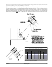
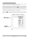
5) Pilot Gas Supply Line
a) The pilot gas supply line consists of a manual shutoff valve, pressure regulator, electric solenoid
valve, back-loaded pressure regulator, and an adjustable gas cock.
b) The gas pressure in this line should be approximately 3.5 inches (8.70 mb) of water column
(W.C.) for natural gas and 1.5 inches (3.73 mb) of water column (W.C.) for liquid propane
(L.P.) gas. This will provide a bushy pilot flame, which produces a signal through the flame rod
that is converted to a 3 DC to 11 volts DC in the burner controller module (BCM).
(1) This flame can be adjusted in two (2) ways.
(a) Pilot Inlet Pressure Regulator
Remove the cap and turn the slotted adjustment screw clockwise (CW) for more gas
and counterclockwise (CCW) for less gas.
(b) Adjustable Pilot Gas Cock
Remove the cap and turn the slotted adjustment screw clockwise (CW) for less gas
and counterclockwise (CCW) for more gas.