


113068-7 www.amdry.com 19
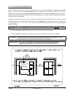
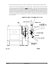
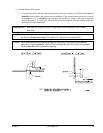
2. Gas Piping
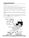
The gas connection to the dryer is made into the 2-1/2” F.P.T. shutoff valve located in the bottom front
corner of the lower heat console.
The gas pressure supplied to the dryer must be between 7 inches (17.41 mb) and 13 inches (32.34 mb)
water column (W.C.) for natural gas or 10.5 inches (26.12 mb) water column (W.C.) for liquid propane
(L.P.) gas.
If the facilities gas pressure is higher than these values, an external pressure regulator must be installed
prior to the dryer to reduce the gas pressure to within the appropriate range.
The dryer must be connected to either natural or L.P. gas indicated on the dryer data label, which is
located in the right hand side of the main electrical enclosure. If your gas supply does not match the type
of gas for which the dryer was built, contact your reseller or the ADC factory.
a. The gas dryer installation must meet the American National Standard...National Fuel Gas Code ANSI
Z223.1-LATEST EDITION, or in Canada, the Canadian Installation Codes CAN/CGA-B149.1 M91
(Natural Gas) or CAN/CGA-B149.2-M91 (L.P. Gas) or LATEST EDITION, as well as local codes
and ordinances and must be done by a qualified professional.
b. The dryer and its individual shutoff valve must be disconnected from the gas supply piping system
during any pressure testing of that system at test pressures in excess of 1/2 psig (3.5 kPa).
Pipe joint compounds that resist the action of natural and L.P. gas must be used.
Test ALL pipe connections for leaks by brushing on a soapy water solution.
WARNING: NEVER TEST FOR LEAKS WITH A FLAME!!!
NOTE: Venting must be controlled in accordance with government and plumbing codes and
regulations to avoid the danger of escaping gas should there be internal leakage. Vent pipes
must be open and the open end protected against entry of foreign matter, including water.