


113068-7 www.amdry.com 9
2. Reassembly Instructions for Dryers Shipped In Three (3) Pieces
When the dryer is shipped in three (3) pieces, the basket (tumbler) and the basket (tumbler) base sections
are shipped as two (2) separate pieces. The heat console section is shipped as the third piece.
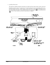
a. Reassemble The Basket (Tumbler) Base Section To The Heat Console Section
Move the heat console section into position by using cables through the eyebolts located at the top of the
section or by using a forklift truck and lifting the section from underneath. The basket (tumbler) base
section is now moved into position with a forklift truck. The seven (7) clearance holes located on the
right side of the basket (tumbler) base section (four [4] holes in front and three [3] at the back of the
section) must be aligned with the seven (7) 3/8-16 tapped holes on the left side of the heat console
section. Use the 3/8-16 x 3” long bolts and the tapered shims supplied with the unit to bolt the section
together.
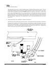
b. Reassemble The Basket (Tumbler) Section Over The Basket (Tumbler) Base
Slowly lower the basket (tumbler) section over the basket (tumbler) base. The four (4) large slots
located on the bottom of the basket (tumbler) section (one [1] slot at each corner of the basket [tumbler]
section) must be aligned with the top of the pistons in the basket (tumbler) base section. Use the four
(4) 1-1/4-12 x 3-1/2” long bolts supplied with the unit to secure the basket (tumbler) section to the
basket (tumbler) base section.
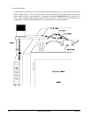
c. Reattach The Control Pendant Arm
Position the control pendant arm to the top front of the heat console section by aligning the clearance
holes in the arm with the 1/4-20 tapped holes on the top of the heat console section. Use the 1/4-20 x
3” long bolts supplied with the dryer to attach the arm to the console.
d. Reconnect the internal air, electric, and water connections (refer to
page 12 through page 17).
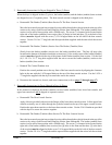
3. Reassembly Instructions for Dryer Shipped in Four (4) Pieces
In this method of shipment the basket (tumbler) section, basket (tumbler) base, lower heat console, and
upper heat console are ALL shipped as separate sections.
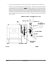
a. Reassemble The Heat Console Section
Apply silicone (provided with unit) to the flanges of the lower heat console section. Lift the upper heat
console section by use of cables through the eyebolts located on the top of the upper console section.
Position the upper heat console over the lower heat console section. Use the 5/16-18 hardware provided
with the dryer to secure the sections together.
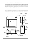
b. Reassemble The Basket (Tumbler) Base Section To The Heat Console Section
Move the heat console section into position by using cables through the eyebolts located at the top of the
section or by using a forklift truck and lifting the section from underneath. The basket (tumbler) base
section is now moved into position with a forklift truck. The seven (7) clearance holes located on the
right side of the basket (tumbler) base section (four [4] holes in the front and the three [3] at the back
of the section) must be aligned with the seven 3/8-16 tapped holes on the left side of the heat console
section. Use the 3/8-16 x 2” long bolts and the tapered shims supplied with the unit to bolt the sections
together.