


38
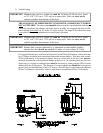
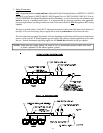
Each valve has five (5) 3/8” F.P.T. ports and two (2) electric solenoid operators, one (1) on each side of the
valve.
To tilt the dryer forward, a 24 volt signal is applied to the rear pistons solenoid connector “12” and no voltage
is applied to the solenoid connector “14.” The internal spool in the valve will move and 80 PSI (5.51 bars)
of air will enter the bottom port of the rear tilting pistons, extending the rear tilting piston rods and tilting the
dryer forward for unloading. The top piston ports are bled to the atmosphere.
To level the dryer, the voltage signals are reversed. No voltage is applied to the “12” solenoid, and 24 volts
is applied to the “14” solenoid. The valve spool will now move so that 80 PSI (5.51 bars) of air is applied at
the top piston ports, while the bottom piston ports are bled to the atmosphere. The piston rod will now retract
leveling the dryer. On rear tilt dryers, the front tilting piston solenoid valve acts in the same manner.
The tilting piston valves are 4-way/5 port/3 position valves. If no voltage is applied to both the “12” and
“14” solenoids, ALL five (5) valve ports are blocked. This means that if the dryer is tilting or leveling and
power to the dryer is shut off, the pistons will lock in position, holding the dryer in a partially tilted position.
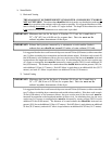
The dryer can be made to tilt faster or slower by adjusting the tilting pistons 3/8” flow control valves which
are located on the pneumatic control panel.
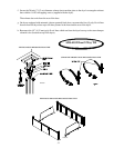
The tilting piston valves and flow control valves are located on the pneumatic plate in the rear of the dryer’s
base.
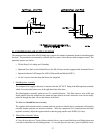
3. Internal/External Pilot Air Supply
On 2-way tilt dryers, a pneumatic safety circuit is incorporated to prevent both front and rear tilting pistons
from extending their rods at the same time. When 24 volts is supplied to the “12” side of the front tilting
piston solenoid valve coil, the round internal spool in the core of the solenoid will move, allowing 80 PSI
(5.51 bars) air to flow into the bottom ports of the front tilting pistons, while the top ports are bled to the
atmosphere. In addition to this 24 volt electrical signal, the spool also requires a 30 PSI (2.06 bars) supply
of compressed air to change its position. This pilot air can either be supplied internally, tapped off the 80 PSI
(5.51 bars) air supply connected to port no. 1 through holes in the body of the solenoid valve or it can be
supplied externally through the 1/8” F.P.T. connection located on either end of the solenoid valve. If no pilot
air is supplied to the solenoid valve, then the spool cannot move, even with voltage supplied to the solenoid
valve.
This can be used to prevent both sets of tilting pistons from extending their rods at the same time. When the
front tilting piston rods are extended, 80 PSI (5.51 bars) air is connected to the bottom piston ports, while the
top piston ports are bled to the atmosphere. So, by tapping the external pilot air supply to the rear tilting
piston solenoid valve off the air line to the front tilting piston top port, whenever the front tilting piston rods
are extended, then there is no pilot pressure available to the rear tilting piston solenoid valve so that its spool
cannot move and the rear tilting piston rods cannot extend even if a 24 volt signal is sent to its “12” side
solenoid valve coil.
The external pilot air supply to the front tilting piston is tapped off the rear tilting piston top port air line so
that whenever the rear piston rods are extended, there is no pilot air supplied to the front tilting piston
solenoid valve and the front tilting piston rods cannot extend. On the solenoid valve supplied on the dryer,
the “12” side valve is externally piloted, while the “14” side valve is internally piloted.
A valve can easily be checked for internal pilot or external pilot by removing the two (2) screws which hold
the solenoid operator onto the valve. For an internal pilot, the “O” ring should be positioned over the
internal pilot supply port. This allows internal pilot air to be supplied to the valve spool. For external pilot,
the solid sealing disc must be positioned on top of the internal port.