


13
ONE BURNER WILL NOT IGNITE AT THE BEGINNING OF A CYCLE
This condition can be caused by the following:
DEFECTIVE DSI (Direct Spark Ignition) MODULE
DEFECTIVE SPARK IGNITOR/FLAME-PROBE ASSEMBLY
DEFECTIVE GAS VALVE
INSUFFICIENT GAS PRESSURE
DEFECTIVE ELECTRICAL HEAT CIRCUIT
Refer to the ladder diagram and the schematics provided with this dryer for reference to the above listed
information.
ONE BURNER WILL NOT IGNITE DURING A DRYING CYCLE
This condition can be caused by the following:
DEFECTIVE DSI (Direct Spark Ignition) MODULE
DEFECTIVE SPARK IGNITOR/FLAME-PROBE ASSEMBLY
DEFECTIVE GAS VALVE
DEFECTIVE ELECTRICAL HEAT CIRCUIT
LOSS OF GAS PRESSURE
Refer to the ladder diagram and the schematics provided with this dryer for reference to the above listed
information.
CONTROL POWER (Indicator/Control Power On Push-Button)
This “green” lighted push-button is for enabling the 24 VAC control voltage to the control circuits of the dryer.
This push-button indicator must be “ON” for the system to load or dry material.
Refer to the ladder diagram included with this AD-410 for the function of this push-button in the 24 VAC control
voltage latching control circuit.
CONTROL POWER (Off Push-Button)
This “red” non-lighted push-button is for disabling the 24 VAC control voltage to the control circuits of the dryer.
Refer to the ladder diagram included with this AD-410 for the function of this push-button in the 24 VAC control
voltage latching control circuit.
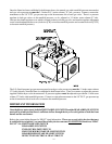
SYSTEM LADDER DIAGRAM
The SYSTEM LADDER DIAGRAM is an overview on the electrical connections of the AD-410. This diagram
is for signal flow information and is a tool to direct an individual in the correct direction for troubleshooting this
dryer.