


6
“EMERGENCY STOP” (E-Stop) BUTTON (Push To Stop/Turn To Release or Pull To Release)
This “red” mushroom push-button, located in the center of the right front control door almost directly under the
Phase 5 microprocessor controller (computer) is a “Push To Stop” and “Turn To Release” type push-button. This
button must be in the released mode to power the dryer (enable the dryer to run).
JOG (Forward/Reverse Push-Buttons)
These two (2) push-buttons, located towards the left hand side of the right front control door, are for either loading
or unloading the tumbler (basket). “JOG” functions are only enabled when the tumbler (basket) section is in a
tilted position.
NOTE: There is a PLC (Programmable Logic Controller) controlled “DWELL TIME” between
forward jog or reverse jog selection to prevent plug starting the tumbler (basket) drive
motor.
LOAD/DRY/UNLOAD (Three [3] Position Selector Switch)
TILT (Off - On) (Two [2] Position Selector Switch)
The “LOAD/DRY/UNLOAD” and “TILT (Off - On)” selector switches work in conjunction with each other. If
the “TILT” selector is in the “OFF” position, an “UNLOAD” or “LOAD” selection will open the front horizontal
doors, allowing an operator to load or unload the tumbler (basket) in the level position.
NOTE: The AD-410 “JOG” feature will respond in the level position. The lint drawer must be
closed for the “JOG” feature to operate.
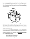
If the “TILT” selector is in the “ON” position, an “UNLOAD” selection will open the front vertical doors and tilt
the tumbler (basket) section towards the front (Rear Up). Likewise, a “LOAD” selection will open the front
horizontal doors and tilt the tumbler (basket) section towards the rear (Front Up).
The “DRY” selection will bring the tumbler (basket) section to a level position and close the front horizontal
doors. Once ALL safe conditions are met (i.e., front doors closed, lint drawer closed, dryer level), an operator will
be able to select a drying cycle on the Phase 5 microprocessor controller’s (computer’s) keyboard (touchpad),
located on the right front control door. Refer to the Phase 5 Operator’s Manual for details.
HEATER FAULT (Indicator/Reset Button) Gas Models Only
During a drying cycle the PLC monitors the status of the Phase 5 microprocessor controller’s (computer’s) “Heat
On/Off” signal, the control status of the front and rear gas valves, and the state of both the front and rear burner
airflow switches. If a fault is sensed, the “HEATER FAULT” indicator and “END OF CYCLE” indicator will
begin to flash at a rate of one (1) per second. Both indicators will flash until the operator presses the “HEATER
FAULT” reset button. For more details on “HEATER FAULT” refer to the AD-410 operation section in this
manual.