


10
2. Check that 80 PSI (5.51 bars) of compressed air is supplied to the dryer and that the “Front Up” solenoid is
being actuated by the PLC (Programmable Logic Controller).
Refer to the PLC signal information included in the ladder diagrams and schematics supplied with the dryer.
DRY
This selection prepares the dryer for a “Material Drying Command” from the Phase 5 microprocessor controller
(computer).
NOTE: Before a drying cycle can be selected, the tumbler (basket) section must be in the level
position and both the front horizontal doors as well as the lint drawer must be closed.
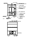
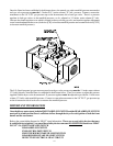
The PLC senses that the dryer is level by the two (2) level switches located on the left hand side of the base section.
One (1) switch is towards the rear of the dryer and the other switch is towards the front of the dryer.
The PLC senses that the vertical doors are closed by the two (2) proximity switches, located at the top center of the
dryer above the doors. These switches are magnetically actuated by magnets located on the doors.
The PLC senses the lint drawer by a push type switch located on the right hand side of the lint drawer door.
IMPORTANT: THE LINT DRAWER and LINT DRAWER GUARD MUST BE CLOSED
BEFORE BRINGING THE DRYER TO A LEVEL POSITION.
If the tumbler (basket) section does not return to a level position:
1. Verify that a “Door Closed” signal is being sensed by the PLC.
2. Check that 80 PSI (5.51 bars) of compressed air is supplied to the dryer and that the “Front Down” or “Rear
Down” solenoid is being actuated by the PLC.
3. Verify that the lint drawer and lint drawer guard is in the closed position. This signal can be easily verified
since it is a PLC input.
Refer to the PLC signal information included in the ladder diagrams and schematics supplied with the dryer.
HEATER FAULT (Indicator/Reset Push-Button) Gas Dryers Only
“HEATER FAULT” refers to a problem in the gas heating portion of the dryer.
The PLC monitors the Phase 5 microprocessor controller’s (computer’s) Heat Off/On signals to the two (2)
individual gas valves that supply the two (2) separate burners.
When a “HEATER FAULT” occurs within the first 25-seconds of the drying cycle, the dryer will go to a “FILL”
message on the Phase 5 microprocessor controller’s (computer’s) display and both the “HEATER FAULT” push-
button and the “END OF CYCLE” light will flash.